 中文简体
中文简体Home / News / Industry News / Magnetic Loop Inductance: A Deeper Look into Precision and Performance
Magnetic Loop Inductance: A Deeper Look into Precision and Performance
In the intricate world of electromagnetic systems, few elements wield as much silent influence as inductance. Within that realm, magnetic loop inductance occupies a unique niche—understated yet indispensable. It underpins the functionality of countless radio frequency (RF) systems, precision sensors, and compact resonant circuits. To grasp its full impact, one must look beyond the textbook definition and understand the nuance of its design, implementation, and effect on performance.
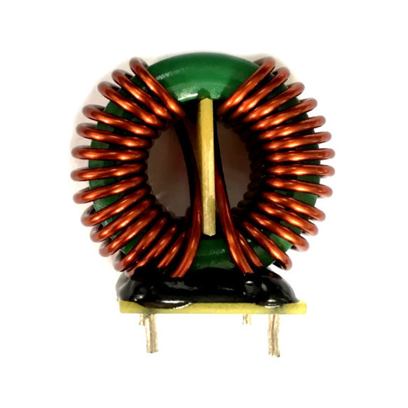
At its core, magnetic loop inductance refers to the property of a closed conductive loop to resist changes in current through the creation of a magnetic field. But unlike conventional inductors that often employ coils and ferrite cores, magnetic loop inductors are usually composed of a circular or polygonal loop of wire or conductive material. These configurations are particularly favored in scenarios where space is limited and efficiency is paramount.
What sets magnetic loop inductance apart is its ability to generate high-Q resonance in a compact footprint. This makes it particularly valuable in high-frequency applications, especially those in the VHF and UHF bands. It’s a critical player in magnetic loop antennas, where the loop itself functions as the inductive element, precisely tuned to resonate at specific frequencies. Such designs are not only compact but also deliver impressive selectivity and low noise profiles—attributes sought after in both amateur and professional radio domains.
One of the key parameters governing magnetic loop inductance is the loop’s physical geometry. Diameter, conductor width, and spacing all play pivotal roles. A larger diameter increases inductance but also affects the tuning range and radiation pattern. Similarly, the choice of material—whether copper, silver-plated tubing, or other low-resistance conductors—directly influences both the efficiency and thermal stability of the loop.
Another dimension to consider is the interplay between inductance and capacitance. In most practical implementations, the magnetic loop is paired with a variable capacitor to form a resonant LC circuit. Fine-tuning this delicate balance enables the loop to target specific frequency bands with remarkable precision. The result: a narrow bandwidth with exceptional noise rejection, ideal for environments plagued by electromagnetic interference (EMI).
From a design standpoint, magnetic loop inductance demands rigorous attention to detail. Even minor variations in solder joints, connector quality, or mounting orientation can induce measurable changes in inductive behavior. Engineers and RF designers often rely on meticulous simulation and empirical testing to optimize performance. Advanced tools such as network analyzers, field strength meters, and 3D EM solvers are routinely deployed to model the loop’s behavior under operational conditions.
Thermal effects must not be ignored. As current flows through the loop, resistive heating can alter the material properties and, consequently, the inductance. High-quality designs account for this, integrating robust thermal management strategies to ensure consistent performance over time and varying conditions.
In essence, magnetic loop inductance is more than just a theoretical concept—it's a dynamic element that interacts with real-world constraints and demands. Its elegance lies in its simplicity; its power, in its precision. In compact communication systems, sensitive detectors, or even stealthy military-grade electronics, the magnetic loop continues to prove its worth. It’s a testament to the fact that in the world of high-frequency engineering, sometimes the smallest loops yield the most significant results.
Previous Post
Mn-Zn High Conductivity Ferrite: Engineered Precision for Power-Dense Performance
Next Post
The H-Shaped Inductor: Engineering Elegance in Electromagnetic Design


