
 English
 한국어
 中文简体
Home / News / Industry News / Nanocrystalline Materials: Grain Size, Properties, and When They Beat Ferrite
Nanocrystalline Materials: Grain Size, Properties, and When They Beat Ferrite
Content
A 20 µm nanocrystalline ribbon can hold a relative permeability above 30,000 and still saturate near 1.2 T. That combination of softness and flux capacity is why the material turns up in common-mode chokes, current transformers and compact 20 kHz power stages, and also why it gets specified in places where a ferrite would have been cheaper and entirely adequate.
What follows covers the meaning of the term at grain level, how the ribbon is produced and annealed, how the numbers stack up against MnZn power ferrite and grain-oriented silicon steel, and which specification lines decide whether a nanocrystalline component works in production or only on the bench.
What Makes a Material Nanocrystalline
A nanocrystalline material is a polycrystalline solid whose grains measure less than roughly 100 nm in at least one dimension. In the magnetic alloys used for components the working range is narrower: 10-20 nm crystallites sitting inside a thin residual amorphous phase.
Definition: a nanocrystalline material is a solid built from crystallites below about 100 nm, so a large share of its atoms sit in grain boundaries rather than inside a perfect lattice. At a 10 nm grain size, that share approaches 30%.
The magnetic behaviour follows directly from that geometry. Once the grain size falls below the ferromagnetic exchange length, a few tens of nanometres in Fe-Si-B-Nb-Cu alloys, the randomly oriented anisotropy of individual grains averages out across many grains. Coercivity drops into the low A/m range and permeability climbs an order of magnitude above conventional crystalline alloys, while the alloy keeps a saturation flux density near 1.2 T.
- Two phases in one material. A typical iron-based grade is about 70-80% crystalline Fe-Si after annealing, with the remainder staying amorphous; the crystallites set the saturation, the chemistry sets thermal stability.
- The name is wider than the magnetics trade uses it. Nanocrystalline ceramics, oxides and metals all belong to the family, but in component catalogues the word nearly always means a melt-spun magnetic ribbon.
- Grain size is a process result rather than a purchase option. Suppliers control it through anneal time and temperature, which is the first thing to verify when parts from two sources behave differently on the same board.
Nanocrystalline is not a synonym for amorphous. An as-cast amorphous ribbon has no grains at all; the anneal that creates the nanocrystals trades a little saturation for far higher permeability, much lower magnetostriction and better temperature stability.
From Molten Alloy to 15 nm Grains
Nearly all magnetic nanocrystalline material is made by rapid solidification followed by a controlled crystallisation anneal: the alloy is quenched into a thin amorphous ribbon, wound into a core, then heat-treated so that 10-15 nm grains precipitate throughout the ribbon.
- Melt spinning. The melt is quenched on a water-cooled copper wheel at roughly 100,000 to 1,000,000 K per second. The ribbon leaves the wheel 18-25 µm thick and fully amorphous.
- Winding. Toroids and cut cores are wound at this stage. The ribbon is ductile before annealing and brittle afterwards, so the final shape is decided early.
- Crystallisation anneal. Holding at 500-560 °C for 30-120 minutes precipitates the nanometre Fe-Si grains. Copper clusters nucleate them and niobium restricts their growth, which is why the size distribution stays narrow.
- Field anneal. A transverse field flattens the hysteresis loop for impedance-style chokes; a longitudinal field produces the square loop used in current transformers and saturable reactors.
- Impregnation and finishing. Epoxy potting, diamond-wheel gapping and dimensional checks. Cutting after annealing is the only practical route, because annealed ribbon will not tolerate bending.
The anneal is where the material is won or lost. A 30 °C overshoot or an extra hour can push grains past 30 nm, and the permeability promised on the datasheet quietly halves.
Property Reality Check: Nanocrystalline vs Ferrite
Nanocrystalline alloys win on saturation flux density and permeability; MnZn ferrite wins on resistivity, shape freedom and price per piece. Neither wins on loss without a frequency attached to the number.
| Property | Nanocrystalline, Fe-based | MnZn power ferrite | Grain-oriented silicon steel |
| Grain size | 10-20 nm | 5-20 µm | 50-200 µm |
| Saturation Bs at 25 °C | 1.2-1.3 T | 0.39-0.53 T | about 2.0 T |
| Relative permeability, typical | 30,000-100,000 | 1,500-15,000 | 2,000-10,000 |
| Resistivity | about 1.15 µΩ·m | 1-10 Ω·m | 0.4-0.5 µΩ·m |
| Curie temperature | about 570 °C | 100-240 °C | about 740 °C |
| Core material thickness | 18-25 µm ribbon | bulk, 0.5-5 mm | 0.23-0.35 mm sheet |
| Relative cost per core | high | low | medium |
The resistivity row is the one engineers underestimate. Ferrite is effectively an insulator, which is why a ferrite core needs no interleaving and can be pressed into almost any shape. Nanocrystalline ribbon is a metal, so eddy currents are controlled by ribbon thickness and by how carefully the layers are insulated from each other.
about 570 °CCurie temperatureagainst 100-240 °C for MnZn
1.15 µΩ·mresistivitya metal, not an insulator
0.75-0.85wound-core stacking factorless copper window than a ferrite bobbin
A core loss figure without frequency, flux density and temperature attached is not a specification. Ask for the measurement point and the DC bias condition before comparing two suppliers.
For designs that stay on the ferrite side of that comparison, the practical starting point is a power grade whose loss curve matches the switching frequency rather than the headline permeability.
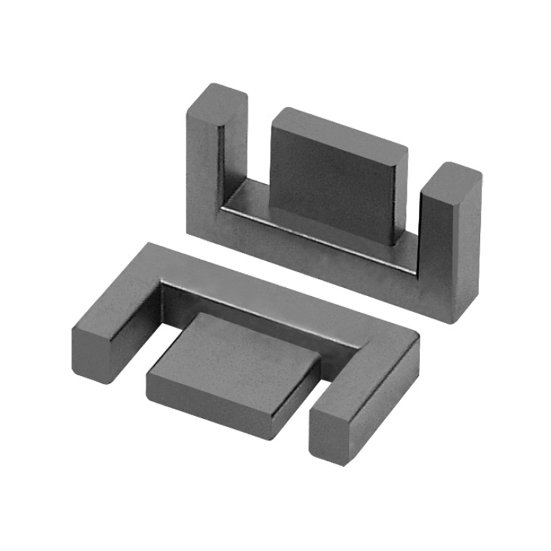
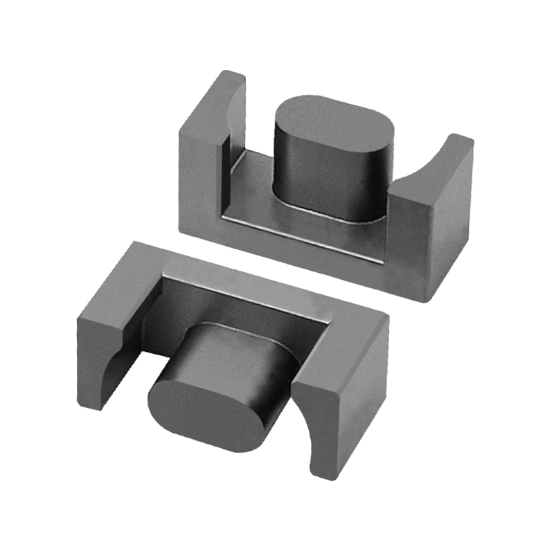
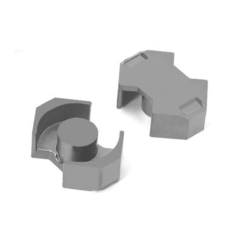
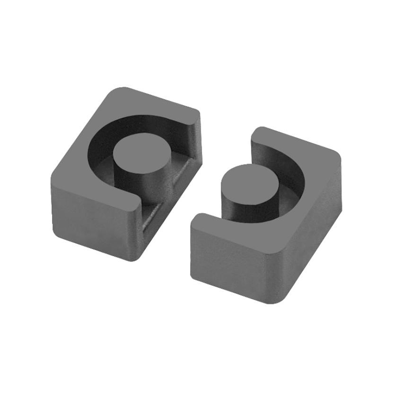
 Mn-Zn Power Ferrite Cores for Power ElectronicsRange of EE, EI, PQ and other Mn-Zn power ferrite cores with grade and AL selection tables for inductors, transformers and motors.View Product →
Where Nanocrystalline Earns Its Price
Nanocrystalline pays for itself wherever high permeability, high saturation and low loss have to coexist in a small volume, and rarely anywhere else.
- Common-mode chokes in EV chargers, solar inverters and motor drives, where one core must deliver high impedance at 150 kHz and survive a large line-frequency bias without saturating.
- Current transformers and residual-current sensors, where a square-loop anneal keeps ratio error and phase shift stable over temperature.
- Medium-frequency transformers in the 10-20 kHz band at tens of kilowatts, where a ferrite core would end up too large or too hot to be practical.
- Wireless power transfer cores and shielding plates between roughly 80 and 200 kHz, where a thin high-permeability layer redirects flux without adding much height.
The same projects usually need a finished wound component rather than a bare core, which is where certified transformer builds matter as much as the ribbon itself.
 Transformer Range for Power, Communication and LightingCategory overview of TV, communication, lighting and new-energy transformers plus inductors, with quote links for finished wound components.View Product →
Specify nanocrystalline when
- 1.2 T saturation is needed in a small footprint.
- Weight or height is the binding constraint.
- DC bias is high but the signal must stay linear.
- The working band sits between 1 kHz and about 200 kHz.
Stay with MnZn ferrite when
- Switching frequency runs above 300 kHz.
- The core needs an E, PQ or pot shape with a bobbin.
- Annual volume is large and cost per piece dominates.
- The part is a 100 kHz PFC choke at moderate flux swing.
A nanocrystalline choke often costs three to five times a ferrite part of the same inductance. That premium is easy to defend in a 3 kW charger and hard to defend in a 20 W adapter.
Specifying and Sourcing Without Surprises
The specification that decides whether a nanocrystalline part works is the one measured at your operating frequency, flux density, temperature and DC bias, not the headline permeability in the catalogue.
- Permeability at the switching frequency. A 100,000 figure measured at 10 kHz can fall below 20,000 by 100 kHz.
- Saturation at 100 °C rather than 25 °C, because both nanocrystalline alloys and ferrites lose flux capacity as they heat.
- Core loss at the actual flux swing, with the DC bias applied and the waveform stated.
- The DC bias curve. A choke that saturates at 60% of rated current is a design failure, not a tolerance.
- Gap tolerance and anneal orientation. A plus or minus 0.05 mm gap shifts inductance more than most teams expect.
Where the design settles into a 100 kHz PFC choke at moderate flux, a power ferrite is still the cheaper answer; the loss behaviour behind that statement is set out in our note on MnZn ferrite in power electronics.
On the ferrite branch of the same comparison, high-conductivity grades are the ones worth putting on the bench next to a nanocrystalline ribbon at 100 kHz.
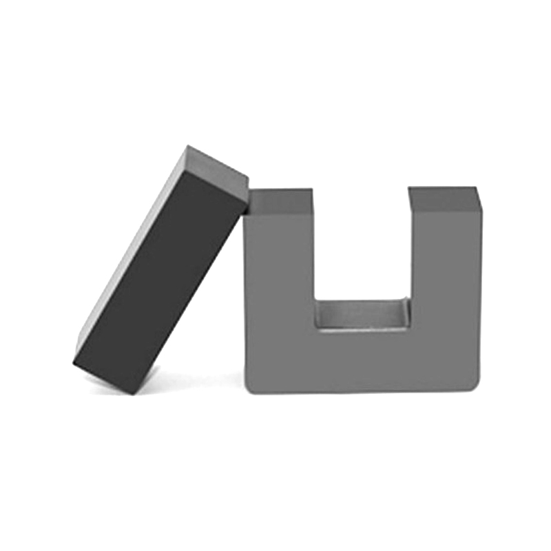 Mn-Zn High Conductivity Ferrite SeriesHigh-conductivity manganese-zinc ferrite series in EE, EI, EPC and other shapes, with dimensions and AL tables for high-frequency inductors, filters and transformers.View Product →
Ask two suppliers for the same part designation and you will often receive two different anneals. Request the anneal profile, the measurement frequency and the DC bias curve with the samples, not after the first production run.
If a side-by-side bench test is the next step, matched ferrite samples and material data can be arranged through the contact page.
Frequently Asked Questions
Are nanocrystalline materials the same as amorphous metals?
No. An amorphous metal has no crystal grains at all. A nanocrystalline alloy starts amorphous and is then annealed so that 10-15 nm crystallites form throughout the ribbon, which raises permeability and lowers magnetostriction while slightly reducing saturation flux density.
At what frequency does nanocrystalline beat ferrite?
Typically between about 1 kHz and 200 kHz, where 1.2 T saturation and permeability above 30,000 allow a much smaller core. Above roughly 300 kHz the metallic ribbon's eddy current losses climb and the size advantage shrinks, so a well-chosen MnZn grade often wins on total loss and cost.
Why is the ribbon annealed after winding instead of before?
Because the anneal makes the ribbon brittle. Winding, cutting and shaping happen while the material is still ductile, and the core is then annealed in its final geometry. Any bending after the anneal cracks the ribbon and raises core loss.
Can nanocrystalline cores be gapped?
Yes, but only by cutting after annealing, usually with a diamond wheel, followed by impregnation. Gapped parts are standard in inductors that must hold DC bias, and gap tolerance is a real cost driver because each cut core is finished individually.
Rule of thumb: if the design needs high permeability and high saturation at the same time, price nanocrystalline first. If it needs a complex shape at high volume, price ferrite first and then check whether the extra permeability buys anything measurable.
Previous Post
No previous article
Next Post
Ferrite Rod Guide: Material Choice, Rod Geometry and Effective Permeability