
 English
 한국어
 中文简体
Home / News / Industry News / Static Var Generator Design: Ferrite Cores, Filter Inductors and Thermal Limits
Static Var Generator Design: Ferrite Cores, Filter Inductors and Thermal Limits
Content
A 100 kVAR static var generator switching at 20 kHz can pull a lagging plant bus back to 0.99 power factor in under two milliseconds, and the same unit will derate or trip if its output filter inductor saturates on a current peak. Converter topology and control loop absorb most of the engineering attention during development; the magnetics are usually specified last and then blamed first when a cabinet comes back from site.
Static var generator (SVG): a shunt-connected, self-commutated voltage-source inverter that continuously injects or absorbs reactive current at the point of common coupling to hold a target power factor or voltage. It has no discrete steps, no contactor transients and no parallel resonance with the network it supports.
What a Static Var Generator Does That a Capacitor Bank Cannot
An SVG controls reactive current in both directions and across a continuous range, while a capacitor bank only offers fixed blocks of leading reactive power.
A 400 V plant is commonly corrected in 20 or 25 kVAR steps. When the load wanders between 8 and 60 kVAR through a welding shift, the controller hunts between steps, each contactor closing adds a transient, and the residual reactive current never settles. The deeper issue is physical: a capacitor's reactive output falls with the square of the system voltage, so at 85 percent voltage it delivers roughly 72 percent of nameplate, exactly when a weak feeder needs more support.
A capacitor bank changes the impedance the network sees. An SVG changes the current it injects. Only the second behaviour can be closed-loop controlled.
Switched capacitor bank
- Step resolution of 20 to 25 kVAR
- Output falls with voltage squared
- Parallel resonance risk with feeder inductance
- Contactor wear and inrush transients
- Low cost, simple maintenance
Static var generator
- Continuous output from zero to rated current
- Constant current until the limit is reached
- No resonance with the network
- Millisecond response for flicker and arc loads
- Higher cost, more magnetic content
That last line is the trade a designer actually pays for. An SVG is a switching converter, and every ampere it pushes into the grid passes through a filter inductor first. The compensation quality a customer sees on a power analyser is set as much by the powder and ferrite in that inductor as by the modulation scheme.
The Magnetic Parts Inside an SVG Cabinet
Every SVG power stage carries at least four magnetic components: the inverter-side filter inductor, the grid-side inductor of the LCL filter, a common-mode choke at the AC terminals, and an isolated gate-drive or auxiliary supply transformer.
Each one fails in a different way and each one is specified with different numbers. The filter inductors carry the full output current plus ripple and dominate the heat load. The common-mode choke sees almost no power-frequency current but decides whether the unit passes conducted emissions. The gate-drive transformer handles nanosecond edges and creepage distances rather than energy.
| Component | Usual core type | What it governs |
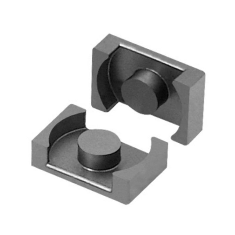
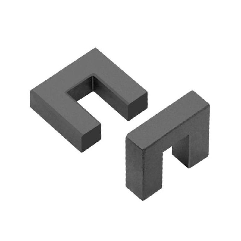
| Inverter-side filter inductor | Gapped MnZn power ferrite, EE, PQ or planar | Ripple current, output current THD, core loss |
| Grid-side inductor (LCL) | Gapped ferrite or distributed-gap powder core | Attenuation of switching harmonics at the coupling point |
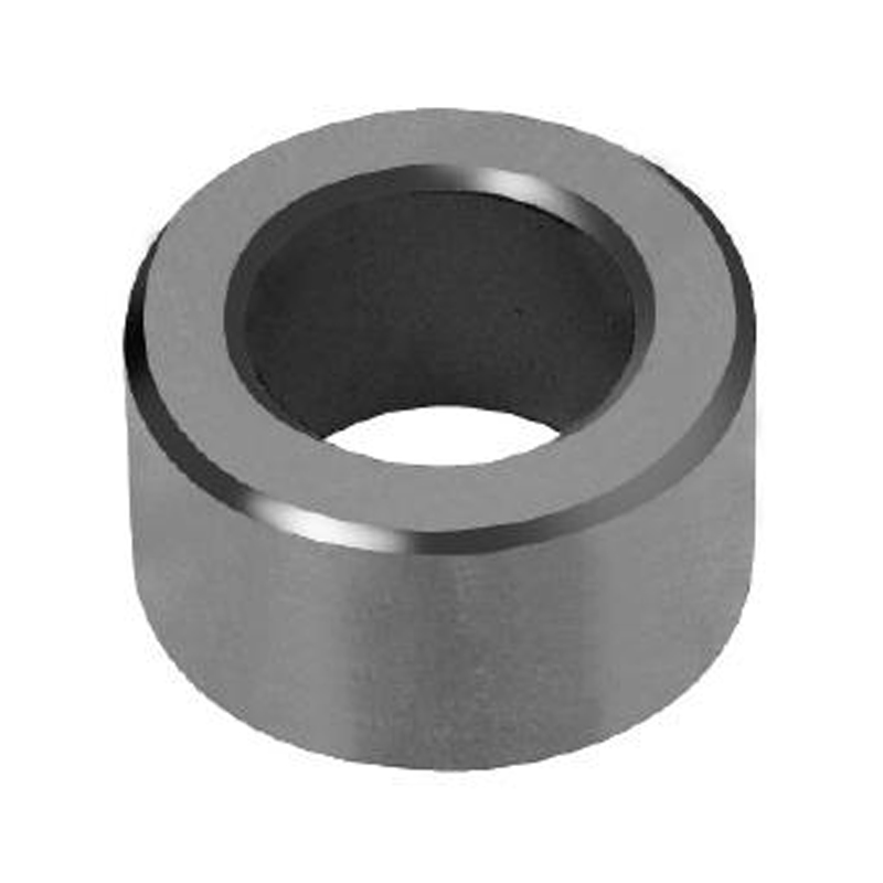
| Common-mode choke | High permeability or high conductivity MnZn ferrite toroid | Conducted emissions from 150 kHz upward |
| Gate-drive transformer | Small high permeability ferrite, often potted | Pulse fidelity, isolation, creepage and clearance |
| Auxiliary supply transformer | Standard MnZn power ferrite | Stable bias rails for control and drivers |
In typical air-cooled 100 kVAR designs the filter inductors take a third or more of the enclosure volume and a comparable share of the internal heat load. Raising switching frequency to shrink them does not remove that heat, it relocates it into the core loss curve.
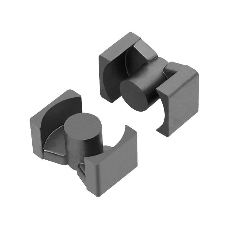
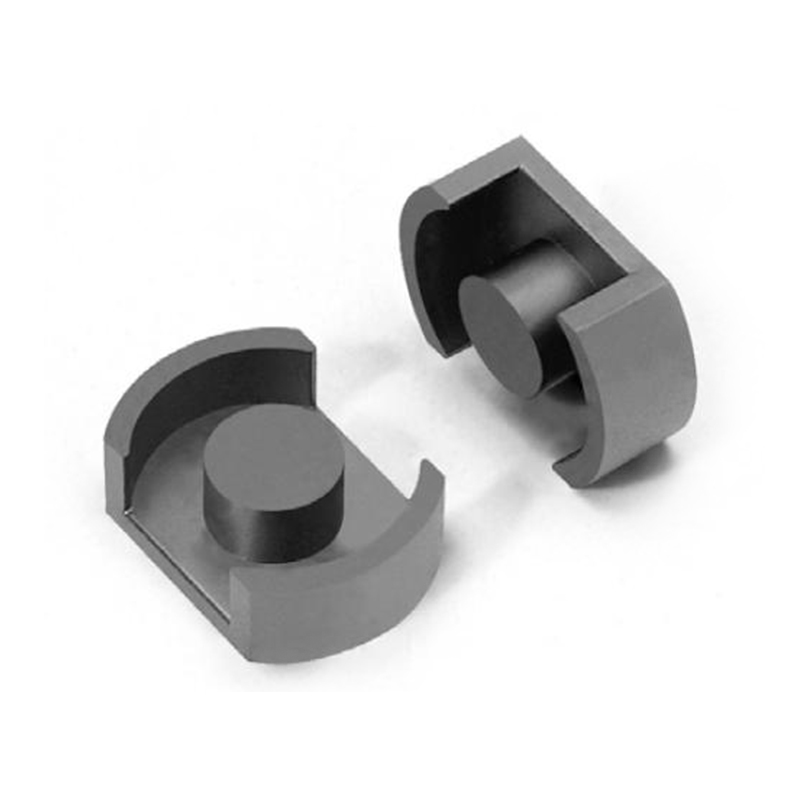
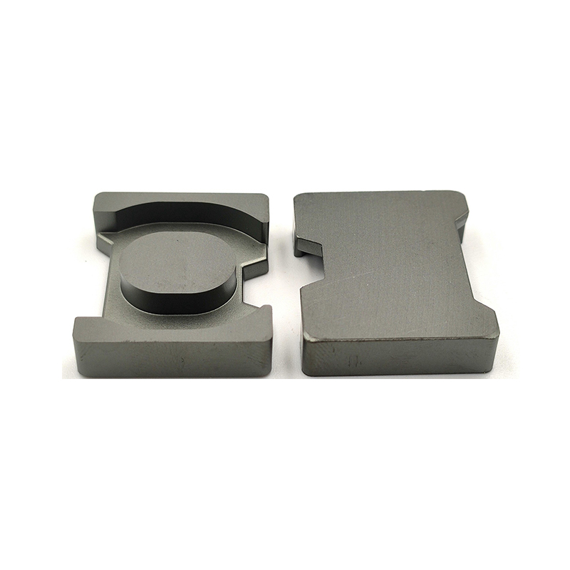
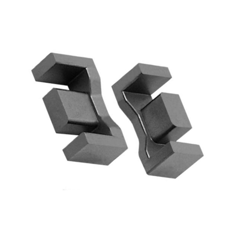
 Mn-Zn Power Ferrite Cores for Inductors and TransformersBrowse power ferrite core families and material grades with dimensions and magnetic parameters, starting with high-saturation, low-loss grades for inductor design.View Product →
Power grades are the natural starting family for the inductor pair, because the design needs a high saturation ceiling and a low loss figure at the same time, and those two requirements pull against each other in any ferrite recipe.
Core Material and Gap Selection for the Filter Inductor
For a 10 to 20 kHz SVG filter inductor, a gapped MnZn power ferrite is normally the right starting point: it combines a saturation flux density near 0.4 T at 100 C with low loss at the moderate flux swing a filter sees.
The inductor carries rated output current plus roughly 20 to 30 percent ripple, so the design is dominated by DC bias rather than by swing. The gap sets the effective permeability, the AL value and how quickly inductance collapses as current climbs. A single ground gap in an EE or PQ core is cheap and predictable; a distributed gap in a planar E-core spreads fringing flux and keeps winding loss lower, at the cost of a wider AL tolerance and more careful specification.
10-20 kHzTypical switching frequency of a low-voltage SVG
0.30 TCommon design ceiling on peak flux at 100 C
+/-3%Typical AL tolerance on a gapped MnZn core
200 C+Curie temperature of standard power grades
Two current points belong on the drawing, not one. The first is rated current, where inductance must still meet the ripple target. The second is the overcurrent or fault point, usually 1.4 to 1.5 times rated, where the core approaches saturation and inductance may legitimately fall by 20 percent. Designing to the second point alone wastes copper and volume; designing to the first alone produces a unit that trips on the first motor start.
Inductance at rated current is a specification. Inductance at fault current is a survivability question.
Loss, Heat and the Limits of the Cabinet
Core loss rises roughly with the 2.4th to 2.8th power of flux density and close to linearly with frequency, so an inductor that runs comfortably on the bench can sit well above its thermal limit once it is sealed inside a cabinet.
The Steinmetz coefficients printed on a material datasheet are measured under sinusoidal excitation at fixed temperature. A real filter inductor sees a triangular ripple riding on a large DC bias, at a core temperature that is itself a function of the loss. That is why the eddy current and hysteresis split matters more than a single headline figure, and why the mechanisms behind eddy current loss in MnZn ferrite are worth understanding before choosing a grade. The practical consequence is a thermal stack that has to be worked through step by step.
Step 1: plant ambient, 45 CA sheet-metal electrical room in summer, no forced ventilation.
Step 2: cabinet rise, plus 10 KSemiconductors, DC bus capacitors and neighbouring inductors heat the internal air.
Step 3: inductor hotspot, plus 25 KCopper and core loss concentrate in the centre limb and inner winding layers.
Result: about 80 C at the windingAt that point saturation flux density is roughly 20 percent below its 25 C value, so the margin must be proven at temperature, not on the bench.
Higher switching frequencies push the design toward materials with higher resistivity, because loss moves out of the hysteresis term and into the eddy current term as frequency climbs.
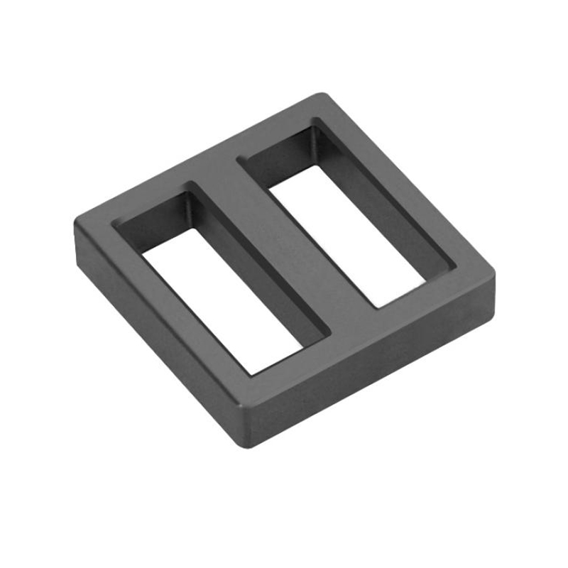
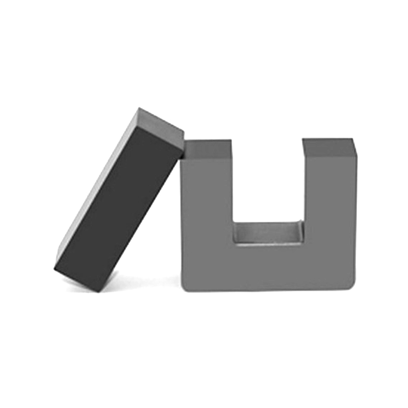 Mn-Zn High-Conductivity Ferrite Core RangeReview high-conductivity Mn-Zn ferrite cores in multiple shapes and grades, with dimensions and AL values for high-frequency inductor, filter and transformer designs.View Product →
That family is where common-mode chokes and gate-drive transformers usually land: small cores, high permeability, and a resistivity high enough that the inter-winding capacitance and the core loss do not fight each other.
Specification and Sourcing Checklist
A usable SVG magnetics specification states the material grade, the gapped AL value with tolerance, the saturation current at 100 C, the loss at the real ripple waveform, the insulation class and the safety approvals. Anything less leaves the supplier to guess, and the guess will be conservative in volume and optimistic in loss.
- Name the grade and the loss points. "Low loss MnZn" is not a grade. Give frequency, flux density and temperature for the loss figure you will accept.
- Fix the gapped AL and its tolerance. State the gap, the measurement conditions and whether the value is for a mated pair or a single half.
- Define inductance at two currents. Rated current and 1.5 times rated, plus the current at which inductance falls to 70 percent of nominal.
- Give the thermal basis. Loss in watts at the actual ripple, the assumed core-to-ambient resistance, and the hotspot temperature you are designing to.
- Close the compliance loop. CQC or UL for finished transformers, batch-level material data and RoHS documentation for cores, plus a traceability reference for each lot.
None of these items is exotic, but together they are the difference between a first prototype that passes EMC on the first attempt and one that goes through three core iterations. If a design is still at the paper stage, it is usually faster to review the specification with a materials supplier than to order samples and infer the answer from temperature readings. The team behind these cores can be reached through the contact page for grade recommendations and sample requests.
 Transformers and Related Inductive ComponentsBrowse transformer series for TV, communication, lighting and new energy plus common-mode, H-shaped and magnetic-loop inductors, with quote options for finished components.View Product →
Where the gate-drive and auxiliary rails are bought as finished wound components rather than built in-house, the same conversation covers creepage, insulation class and the certification path for the transformer family.
Frequently Asked Questions
Is a static var generator the same thing as a capacitor bank?
No. A capacitor bank supplies fixed blocks of leading reactive power that shrink as voltage falls. An SVG is an inverter that injects or absorbs reactive current continuously and in both directions, so it can hold a target power factor through voltage sag and load swings that would leave a stepped bank hunting.
Do SVG filter inductors use ferrite or powder cores?
Both appear in production units. Gapped MnZn power ferrite is common where high inductance and low loss at moderate flux swing are needed; distributed-gap powder cores are chosen when soft saturation and high DC bias tolerance matter more than raw permeability.
Why does temperature matter so much for MnZn ferrite in an SVG?
Saturation flux density falls by roughly 20 percent between 25 C and 100 C, while core loss has its own minimum somewhere in the 60 to 100 C band. A design that is safe at room temperature can saturate at 80 C in a sealed cabinet, so all margins should be evaluated at the expected hotspot.
Can one SVG also reduce harmonics?
Units with a fast current loop and sufficient bandwidth can share the task, but the filter inductor then has to pass harmonic current without adding loss or saturating on the crest factor. If harmonic mitigation is a primary requirement, the inductor specification changes and should be written for it from the start.
Previous Post
No previous article
Next Post
Ferrite Rod Aerial Design: Effective Permeability, MnZn Grades and Winding