
 English
 한국어
 中文简体
Home / News / Industry News / Ferrite Rod Aerial Design: Effective Permeability, MnZn Grades and Winding
Ferrite Rod Aerial Design: Effective Permeability, MnZn Grades and Winding
Content
- 1 What a ferrite rod aerial actually does
- 2 Effective permeability sets the signal, not the data sheet
- 3 Manganese-zinc grades: what to specify
- 4 Winding, Q and tuning: where sensitivity is won or lost
- 5 Ferrite rod or air-core loop?
- 6 Sourcing rods and cores: what to verify before a run
- 7 Frequently asked questions
A 100 mm manganese-zinc rod quoted at an initial permeability of 1000 will not measure anywhere near 1000 once you wind a coil on it and sweep it at 1 MHz. The number you actually get, often somewhere between 20 and 60, is the rod's effective permeability, and it decides whether a ferrite rod aerial pulls in a weak station or drowns in its own noise.
That gap between the catalogue figure and the working circuit is where almost all rod aerial design happens. What follows covers what the rod does to an incoming wave, which material to specify, how to wind and tune it, and what to check before a production lot is committed.
What a ferrite rod aerial actually does
A ferrite rod aerial, usually called a loopstick, is a coil wound on a cylindrical ferrite core that concentrates the magnetic component of an incoming wave so a physically short antenna can deliver a usable signal.
Definition
A ferrite rod aerial is a receiving antenna in which a high-permeability ferrite rod acts as a flux concentrator for a coil wound around it, raising the effective capture area far beyond the physical size of the winding.
The rod responds to the magnetic field of the wave, not to its electric field. Induced voltage rises with frequency, effective permeability, effective core area and turns, and nothing in that relationship depends on the antenna being a resonant length. That is why a rod of a few centimetres works at 1 MHz, where a quarter-wave whip would need to be 75 metres tall.
- Directivity is figure-eight in shape: response peaks broadside to the rod and falls into a deep null along its axis, which is how portable receivers reject a nearby station.
- Size is the whole point. Long wave, medium wave, 60 kHz time signals, 125 kHz RFID readers and 8.2 MHz security gates all use rods because the alternative aperture would be metres across.
- Bandwidth is set by the tuned circuit around the coil, so sensitivity and selectivity are traded against each other with one capacitor.
- There is no gain. A rod is passive; every decibel of usable output comes from the following amplifier and its impedance match.
Effective permeability sets the signal, not the data sheet
Effective permeability describes how much flux the finished rod actually concentrates, and for a slender rod it is only a small fraction of the material's quoted initial permeability, because the open magnetic path creates a strong demagnetising field.
The demagnetising relation is close to this: effective permeability equals initial permeability divided by one plus N times the quantity initial permeability minus one, where N is the demagnetising factor along the rod axis. N falls as the rod grows longer relative to its diameter, so length-to-diameter ratio, not material grade, is the first variable to fix. The relationship between rod geometry and measured permeability is worth reading in more depth alongside a ferrite rod geometry and effective permeability guide.
Relative signal pickup against rod slenderness
Move from a 1000 permeability grade to a 5000 permeability grade on a rod with a length-to-diameter ratio of 15 and you will measure a gain of a few tenths of a decibel. Double the rod length instead and effective permeability roughly doubles. The high-permeability part also lowers the self-resonant frequency of the winding and drops Q, because the same composition that concentrates flux stores more energy per unit volume.
Rule of thumb: for rods between 100 mm and 200 mm long, a length-to-diameter ratio of 12 to 25 captures most of the available gain. Past that point, extra length costs more than it returns.
Sliding the coil along the rod is the other lever. A winding at the centre sees the highest effective permeability and gives maximum inductance; pushing it toward one end drops inductance quickly and predictably, which makes it a free tolerance adjustment during tuning.
Manganese-zinc grades: what to specify
For long-wave and medium-wave receiving rods, specify a manganese-zinc ferrite with initial permeability between roughly 400 and 1000 and a low loss tangent at the band centre. Nickel-zinc becomes relevant only when the operating frequency climbs above a few megahertz.
| Material family | Typical initial permeability | Usual band | Design note |
| MnZn high permeability | 1000 to 10000 | 50 kHz to 1 MHz | Highest raw sensitivity, lowest Q, strongest temperature drift |
| MnZn standard and power grades | 400 to 2500 | 100 kHz to 3 MHz | Flatter loss, wider availability, easier to tune across a band |
| NiZn | 5 to 1500 | 1 MHz to 100 MHz | Lower permeability but usable Q well above the MnZn ceiling |
Resistivity matters once the winding sits above a few megahertz, because eddy currents inside the core turn signal into heat. That is the region where the manganese-zinc high conductivity family deserves evaluation, and where measured loss curves at the working frequency are worth more than a nominal permeability figure.
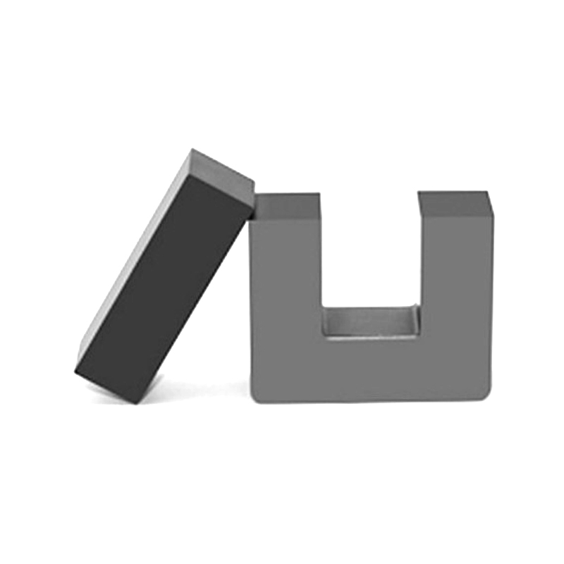 Mn-Zn High Conductivity Ferrite Core SeriesReview the Mn-Zn high conductivity ferrite series with multiple core shapes and AL values for high-frequency inductor, filter and transformer designs.View Product →
Temperature is the specification most often missing from the purchase order.
Initial permeability of high-permeability manganese-zinc grades changes noticeably between -20 and +60 degrees Celsius. A rod tuned at room temperature in a plastic case will not sit at the same inductance inside a warm vehicle or a sealed enclosure. Ask for the permeability-versus-temperature curve and tune at the temperature the product actually sees.
Winding, Q and tuning: where sensitivity is won or lost
Winding placement and coil Q usually move measured sensitivity more than the core grade does, so the finished rod should be measured rather than calculated.
- Fix the blank. Choose length and diameter from the length-to-diameter target, then check straightness, diameter tolerance and end chipping before anything is wound.
- Wind a test coil. Stranded Litz wire of 5 to 10 strands suits medium wave; keep the winding length below about one third of the rod so the ends still gather flux.
- Set the inductance. With a 10 to 270 pF variable capacitor, 260 to 330 microhenries covers roughly 530 kHz to 1.7 MHz, and scaling turns by the square root of the inductance ratio lands close on the first attempt.
- Trim by sliding. Move the coil toward one end to lower inductance, back toward the centre to raise it. This is the cheapest tolerance adjustment available on a rod.
- Measure and fix. Read inductance and Q at the band centre with the real capacitor in circuit, then secure the coil with wax or a compliant adhesive that does not stress the ferrite.
Coil Q on medium wave typically lands between 100 and 300 once the rod, wire and capacitor are all in place. A tuned rod presents a high impedance, so the first stage after it needs a high input impedance, either a junction FET or a step-up winding, otherwise the loaded Q collapses and selectivity with it.
Tolerance check
A plus or minus 10 percent inductance spread from core permeability and winding count can push both band edges outside the range of a small variable capacitor. Verify tuning at each band end using the worst-case rod and the worst-case capacitor.
Ferrite rod or air-core loop?
A ferrite rod delivers far more signal than an air-core loop of the same volume at medium wave, but the air loop has higher Q, no core loss, and can be rotated to null interference.
Ferrite rod aerial
- High signal per unit volume: a 100 mm rod outperforms a loop many times its size
- Self-supporting, light and cheap at volume
- Core loss limits Q, typically 100 to 300
- Permeability drift with temperature and lot
- Brittle: chipped ends change inductance
Air-core loop
- High Q and low loss with no magnetic material to drift
- Predictable, repeatable inductance
- Rotatable, so a local interferer can be nulled out
- Needs a frame hundreds of millimetres across at medium wave
- More turns, more copper, more mechanical bulk
The decision usually comes down to packaging. Handheld, pocket and automotive receivers take the rod because a loop will not fit. Bench receivers and loop-antenna designs stay with air cores where a 300 mm frame is acceptable and interference rejection matters more than size.
At 125 kHz RFID and 8.2 MHz security gates the rod is chosen for size, not raw sensitivity. Read range in those systems is set by the reader field and the tag Q, so squeezing another five percent of effective permeability out of the ferrite rarely changes the outcome.
Sourcing rods and cores: what to verify before a run
Ask for measured initial permeability with its tolerance band, loss tangent at your operating frequency, and the permeability-versus-temperature curve; a datasheet that gives only a nominal value cannot support a tuned-rod design.
12 to 25length-to-diameter target for receiving rods
1/3maximum winding length relative to the rod
100 to 300typical Q for a wound medium-wave rod
Rods are normally pressed and sintered to near-final shape rather than ground, because grinding a long, thin, abrasive ceramic is slow and expensive. That means dimensional tolerance, straightness and end condition all come out of the tooling, and all of them change the winding and the effective permeability. Inspect a sample lot for length tolerance, visible cracks and chipping before tooling is cut.
If you press your own rods, the powder grade and calcination control shrinkage and final permeability, so a change of powder lot is a change of inductance. Suppliers who can hold a material grade across lots, such as those offering soft magnetic ferrite powder alongside finished cores, are the ones worth an early conversation.
Batch consistency beats a headline number. A three percent lot-to-lot permeability spread is easier to live with than a spectacular single-lot result you cannot repeat, especially when a variable capacitor has to cover the band on every unit built. Order samples from two lots through the contact page before committing to a run.
Frequently asked questions
Does a ferrite rod aerial need a ground connection?
No. The rod is a magnetic antenna and does not depend on a ground plane for its sensitivity. Keeping the rod clear of metal, by at least one rod diameter, matters more than grounding, because nearby conductors distort the field and reduce Q.
What permeability should an AM loopstick use?
A manganese-zinc grade with an initial permeability of 400 to 1000 is the practical choice. Because the demagnetising factor dominates a slender rod, going much above 1000 gains very little signal while costing Q and temperature stability.
Can a ferrite rod be cut to length?
It can be cut with a diamond blade, but expect chipping and a measurable shift in effective permeability, plus possible micro-cracks that open later. Specifying the correct length at the pressing stage is cheaper and far more consistent.
Why does inductance drop when the coil sits near the rod end?
Flux concentration is highest at the middle of the rod and falls toward the ends, so a coil near the tip links less flux and therefore shows lower inductance. That behaviour is repeatable enough to use as a deliberate tuning adjustment.
Short version: fix geometry first, then material, then winding, and measure every step on the finished rod rather than in a spreadsheet.
Previous Post
No previous article
Next Post
Standard Inductor Values Explained: E12 and E24 Ladders, Codes, and Core Turns