
 English
 한국어
 中文简体
Home / News / Industry News / Standard Inductor Values Explained: E12 and E24 Ladders, Codes, and Core Turns
Standard Inductor Values Explained: E12 and E24 Ladders, Codes, and Core Turns
Content
A part marked 100 uH with a plus or minus 10 percent tolerance may legitimately measure anywhere between 90 and 110 uH, and a plus or minus 20 percent part anywhere between 80 and 120 uH. That window, not the printed number, is what the circuit has to survive, and the standard value ladders exist so those windows overlap in a pattern any distributor can stock and any designer can second-source.
The ladders are not a marketing habit. They come from IEC 60063, the preferred number system shared with resistors and capacitors, which is why 4.7 uH, 47 uH and 470 uH sit on distributor shelves while 17 uH is almost always a special order with a winding setup charge attached.
What Standard Inductor Values Actually Define
Standard inductor values are the E-series preferred numbers applied to inductance: a repeating set of 6, 12, 24 or 96 steps inside each decade, spaced so the tolerance band of one nominal value nearly touches the band of the next.
E6, E12, E24 and E96 are not four product families. They are four resolutions of the same logarithmic ladder, and the resolution you can actually buy is limited by how tightly a part can be wound or gapped.
6E6 steps per decade, roughly plus or minus 20 percent
12E12 steps, the working standard for power chokes
24E24 steps, used where inductance sets a corner frequency
96E96 steps, mostly thin-film and chip inductors
For a wound power inductor the practical resolutions are E12 and E24. A 5 percent inductance window sounds precise, but it loses meaning once bias, temperature and gap tolerance are applied. MnZn ferrite permeability drifts with temperature, AL values carry their own spread, and a choke that measures 100 uH at 25 C and near-zero bias can fall to 60 uH at rated current.
The number that decides whether a converter stays in continuous conduction is the inductance under load, not the nominal printed on the label.
The E12 and E24 Ladders You Will Actually Order From
E12 at plus or minus 10 percent and E24 at plus or minus 5 percent cover almost every catalogue power choke and filter inductor, and E12 alone accounts for the bulk of stocked inductance between 1 uH and 1 mH.
| Nominal (uH) | Minimum (uH) | Maximum (uH) | Marking |
| 10 | 9.0 | 11.0 | 100 |
| 12 | 10.8 | 13.2 | 120 |
| 15 | 13.5 | 16.5 | 150 |
| 18 | 16.2 | 19.8 | 180 |
| 22 | 19.8 | 24.2 | 220 |
| 27 | 24.3 | 29.7 | 270 |
| 33 | 29.7 | 36.3 | 330 |
| 39 | 35.1 | 42.9 | 390 |
| 47 | 42.3 | 51.7 | 470 |
| 56 | 50.4 | 61.6 | 560 |
| 68 | 61.2 | 74.8 | 680 |
| 82 | 73.8 | 90.2 | 820 |
Each E12 step is about 1.21 times the value below it, which matches a tolerance window roughly 1.22 wide. Consecutive nominals therefore sit side by side with almost no gap and almost no overlap, so moving from 39 uH to 47 uH shifts the design window upward without ever leaving the stocked list.
E24 halves the step to about 1.10 and adds 11, 13, 16, 20, 24, 30, 36, 43, 51, 62, 75 and 91 to each decade. It earns its place where inductance sets a frequency rather than a ripple current:
- LC filters whose cutoff must stay inside a narrow band across production batches
- Resonant tanks and snubbers where 10 percent detuning is paid for in efficiency
- Current-sense and EMI filters that must match a calculated corner frequency
E66
E1212
E2424
E9696
Values available per decade. Bar length is scaled for readability, not plotted to a linear axis.
E48 and E96 inductance values are rare in wound components. Outside thin-film and multilayer chip inductors, a request for one usually means a custom winding and a lead time, not a catalogue line item.
Reading the Marking Before You Trust the Value
A three-digit SMD inductor code is inductance in microhenries: the first two digits are the significant figures and the third is the number of zeros, with the letter R standing in for the decimal point.
| Marking | Value | Reading rule |
| 1R0 | 1.0 uH | R replaces the decimal point |
| 4R7 | 4.7 uH | E12 value, very widely stocked |
| 100 | 10 uH | 10 with zero additional zeros |
| 220 | 22 uH | 22 followed by one zero |
| 470 | 47 uH | E12 and E24 shared value |
| 101 | 100 uH | 10 followed by two zeros |
| 221 | 220 uH | 22 followed by two zeros |
| 102 | 1000 uH | Equals 1 mH at the top of the range |
| 222 | 2200 uH | Equals 2.2 mH |
Tolerance rides on a letter suffix: J is plus or minus 5 percent, K is 10 percent, M is 20 percent. A part marked 470K is therefore 47 uH at 10 percent, not 470 uH at any tolerance.
The digits 101 mean 100 uH on an inductor and 100 ohm on a resistor. The two component families share a marking convention, not a value.
Leaded parts are harder to decode. Some use color bands read in microhenries, some in millihenries, and the fourth band is tolerance on some ranges and a temperature coefficient on others. When a marking cannot be resolved to a decade, measure the part at the frequency it will actually see: a high-permeability ferrite core can read very differently at 100 kHz than at 1 kHz.
Turning a Standard Value into Turns on a Ferrite Core
A standard inductance becomes a real part only when the core geometry and AL value allow it, and the governing relationship is turns equals the square root of inductance divided by AL, with inductance in nanohenries and AL in nanohenries per turn squared.
N = square root of (L divided by AL)
100 uH target on AL 4000 nH per turn squared = 5 turns
100 uH target on AL 4000 nH per turn squared = 5 turns
Worked example: a 100 uH target on a core with AL of 4000 nH per turn squared needs five turns. If that AL carries a plus or minus 25 percent spread, the same five-turn winding lands between 75 uH and 125 uH, straddling the E12 values of 82 uH and 120 uH. That is exactly why gapped cores with tight AL tolerance are specified wherever inductance sets a cutoff or a ripple limit.
- Fix the window, not the nominal. Decide the acceptable inductance band at operating current and at the temperature extremes before choosing a number from the ladder.
- Size the core from stored energy. Peak energy storage set by inductance and peak current squared decides core volume far more than the nominal inductance does.
- Convert to turns and round to a whole number. A design that calculates to 4.5 turns will be built as 4 or 5, so the delivered value moves by more than the tolerance band.
- Verify at bias and at temperature. Confirm that inductance at rated current still sits inside the window you fixed in step one.
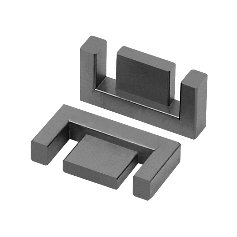
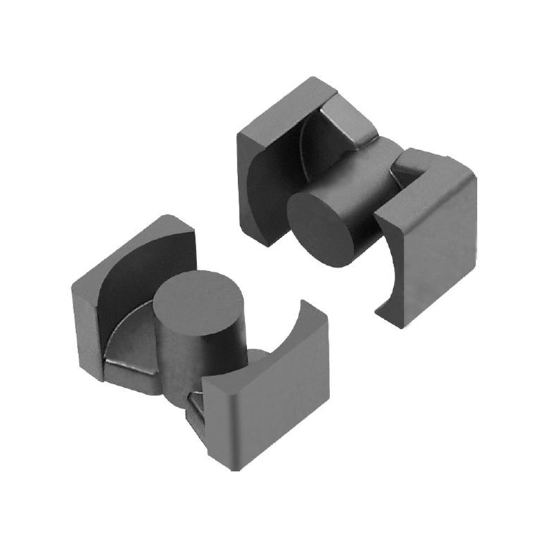
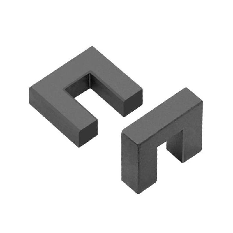
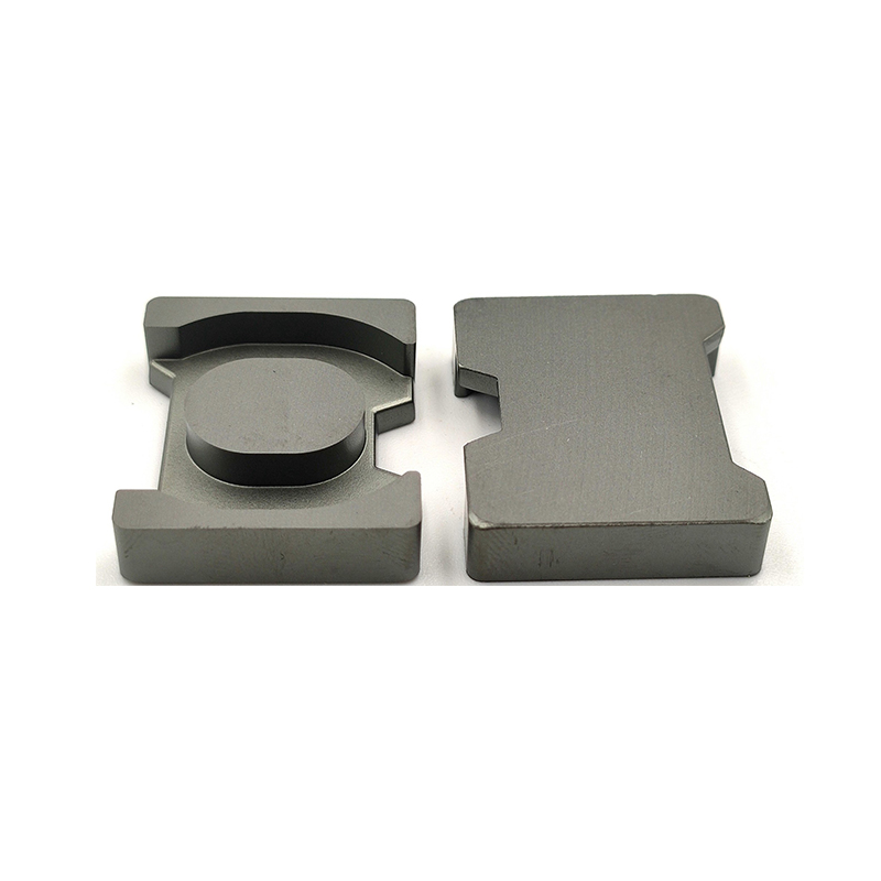
 Mn-Zn Power Ferrite Core SeriesReview EE, EF, EC, EFD, EI, EQ and PQ cores with dimensions, effective parameters and ±25% AL values for power designs.View Product →
Rounding matters more than it looks. Halving the turn count quadruples the AL required, so a 4.5 turn design lands on one of two values rather than the printed nominal, and the adjustment is made with a gap, not with a turn. The behavior of gapped and ungapped MnZn ferrite cores is worth checking early, because a gapped core and an ungapped core at the same nominal inductance behave like two different materials once bias current is applied.
When a Non-Standard Value Is the Right Answer
A non-standard inductance is worth the setup cost when a standard value forces a larger core, extra turns, or a saturation margin that costs more than the custom part.
Stay on E12 or E24
- Power chokes between 1 uH and 1 mH with ripple as the main constraint
- Designs carrying 20 percent or more inductance headroom
- Projects that need a second source inside a week
- EMI filter chokes where the exact corner frequency is not critical
Specify a custom value
- Cutoff or resonance that must not drift between production runs
- Core window too small for the next step up the ladder
- Matching networks where two percent error is measurable
- Existing qualified designs already built around 17 uH or 33.5 uH
The cost of a non-standard value is rarely the part itself. It is the pressing tool, the gap grinding step and the incoming inspection routine that the off-the-shelf value would have absorbed for you.
A supplier that runs its own powder line can change the material first and gap the core second, which is what makes an off-ladder value practical at all rather than an exercise in hand winding.
 Mn-Zn Soft Magnetic Ferrite Powder GradesExplore YR-series Mn-Zn soft ferrite powders with downloadable datasheets, suited to custom magnetic components defined by material and test conditions.View Product →
- Minimum order quantity: a custom gap is usually quoted in thousands of pieces, not hundreds.
- Tooling and setup: new pressing tools or grinding fixtures add fixed cost before the first good part.
- Lead time: samples are quick, but production runs typically stretch well beyond catalogue delivery.
- Test definition: frequency, signal level, bias and temperature must be written down, or the part cannot be second-sourced later.
Custom does not mean arbitrary. Write the requirement as a window with a test condition, for example 17 uH plus or minus 5 percent at 100 kHz, 0.1 V and 25 C on a defined fixture, and the part becomes reproducible instead of a one-off conversation.
Standard Inductor Values: Quick Answers
Is 4.7 uH a standard inductor value?
Yes. 4.7 uH appears on both the E12 and E24 ladders in the one to ten microhenry decade and is one of the most widely stocked values in molded and shielded SMD families. In three-digit marking it reads as 4R7, and a tolerance suffix such as 4R7K means plus or minus 10 percent.
Why are inductors usually E12 rather than E24?
Because of what can be held in production. A ferrite core with an air gap realistically holds plus or minus 10 percent once gap tolerance, permeability spread and temperature drift are combined, so an E24 step of about 10 percent would produce overlapping windows that no process can sort. E24 becomes practical mainly in chip inductors, where the winding is printed or photo-etched rather than wound.
Can I order a 17 uH inductor?
Yes, but expect it as a custom gapped core or a trimmed winding rather than a shelf item. Specify the window, the measurement frequency and the bias condition, and confirm that the supplier controls both the material grade and the gap, since changing either one alone shifts the delivered inductance.
Does a larger standard value always filter better?
No. A larger inductance lowers ripple current, but it also raises turn count, copper resistance and core loss, and it pushes self-resonance lower. Past a point the part saturates earlier under DC bias and filters worse than the smaller nominal would have. The right value is the smallest one that keeps ripple inside budget with margin at the operating current.
If the value your design needs is not on the E12 or E24 ladder, describe the window and the test condition and our engineering team will confirm which core geometry and material grade can hold it. Send the electrical requirement here.
Previous Post
No previous article
Next Post
Nanocrystalline Materials: Grain Size, Properties, and When They Beat Ferrite