
 English
 한국어
한국어 中文简体
中文简体Home / News / Industry News / Custom Magnetics Design: Practical Engineering, Thermal, and Sourcing Guide
Custom Magnetics Design: Practical Engineering, Thermal, and Sourcing Guide
Content
A custom magnetic program almost always starts with a constraint that no catalogue part satisfies. A 200 kHz LLC stage needs 22 uH at 6 A of DC bias, the board leaves 4 mm of height above the surface, and the shutdown threshold sits at 118 C. Stock inductors inside that envelope run hot, saturate early, or fail the creepage requirement. Custom magnetics design is the work of turning those numbers into a wound component that holds its inductance, stays inside its thermal budget, and can be built again next quarter with the same result.
What Custom Magnetics Design Actually Means
Custom magnetics design is the process of translating a customer-specific electrical, thermal, and mechanical requirement into a magnetic component built for that requirement alone, rather than selecting the nearest catalogue part and accepting its compromises.
A custom magnetic is not a catalogue part with a new part number. It is a core material, a core geometry, an air gap, a winding build, and a termination scheme chosen together so that one set of constraints is met without breaking the others.
The scope reaches further than most buyers expect. A single custom program touches several independent decisions at once:
- Core material grade, including initial permeability, saturation flux density, and core loss at the operating frequency
- Core shape and air gap, which set the inductance value, the DC bias behaviour, and the leakage inductance
- Winding window usage, wire gauge, and interleaving, which drive copper loss and proximity effects
- Termination style, pin out, and mounting geometry, which decide whether the part fits the board at all
- Insulation system, creepage, and clearance, which determine whether the design clears safety review
Each of those choices trades against the others. A wider gap raises the saturation margin but increases fringing loss near the winding. Finer wire lowers skin effect loss but fills the bobbin faster and pushes the build height up. The design task is finding the combination that clears every constraint, not maximising any single figure of merit.
When Off-the-Shelf Parts Stop Working
Off-the-shelf magnetics stop working when several constraints tighten at the same time, not when one of them does.
A single tight specification is usually solvable from a catalogue. Two are awkward. Three or more, and the selection table runs out of rows. The failures tend to fall into a handful of recognisable patterns:
- Inductance collapses under DC bias because the core grade has limited superposition performance at the rated current
- Winding temperature climbs past the insulation class rating once core loss and copper loss are added together
- The available footprint forces a core size that cannot physically hold the required turns of the required wire
- Creepage and clearance fail the safety standard after the pin out is fixed by the board layout
- Radiated noise from leakage inductance cannot be filtered without adding components the enclosure has no room for
Standard Catalogue Part
- Optimised for a family of applications, never for one
- Fixed core geometry and fixed air gap
- Fixed pin out and fixed winding build
- Inductance tolerance set by the supplier, not by your loop
- Lead times driven by someone else's forecast
Custom Magnetic Design
- Optimised for one converter, one enclosure, one thermal path
- Gap tuned to hold inductance at the actual bias current
- Pin out and height matched to the board and the lid
- Tolerance budget allocated to whichever parameter actually matters
- Material grade chosen for the switching frequency in use
The practical trigger is rarely a single out-of-spec number. It is the moment two or three specifications can no longer be satisfied by the same catalogue line item.
Core Material Choice Drives the Whole Design
Core material is the first decision in custom magnetics design, because it fixes the loss budget, the bias behaviour, and the usable frequency window before any winding geometry is considered.
Manganese zinc ferrite remains the default for power conversion between roughly 20 kHz and a few hundred kilohertz. Within that family, grades diverge sharply. A low-loss power grade keeps core loss down at elevated flux density, which suits flyback and forward transformers running hard. A high-conductivity grade pushes resistivity up so eddy currents stay small, which matters as switching frequency climbs and AC resistance starts to dominate total loss.
20 - 200 kHz Typical working window for MnZn power ferrite grades
390 - 500 mT Saturation flux density range at room temperature
80 - 100 C Temperature band where core loss usually reaches its minimum
The loss minimum matters more than the datasheet headline. A design that runs the core at 40 C pays a penalty that a design running at 90 C does not, even with identical material. If the enclosure cannot hold the core near its loss minimum, the material choice has to compensate, often by moving to a lower-loss grade or accepting a larger core.
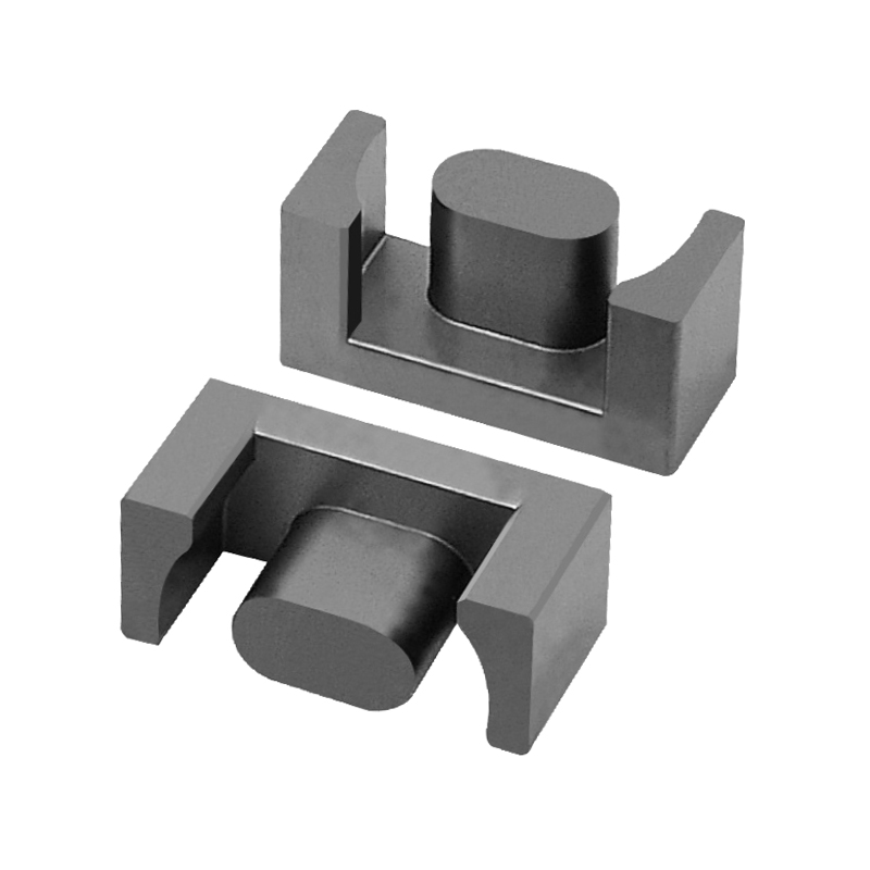
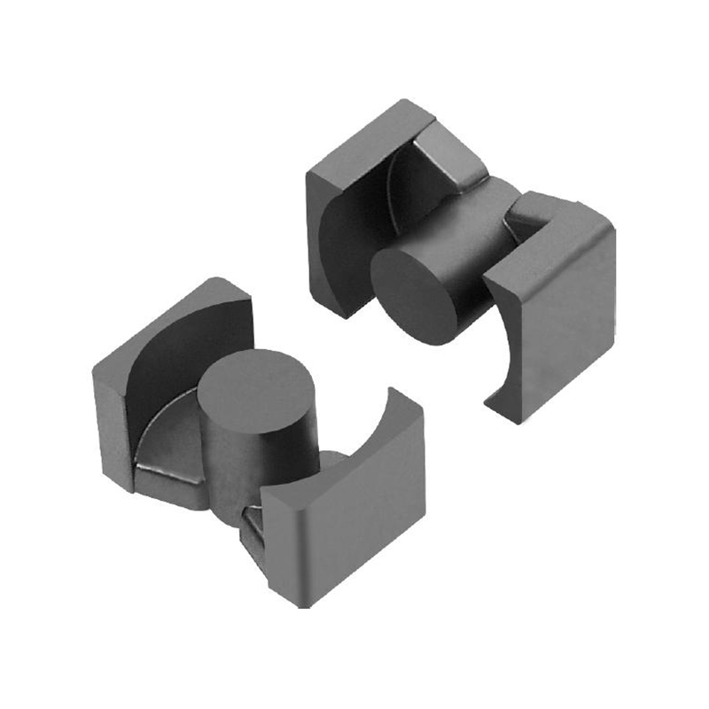
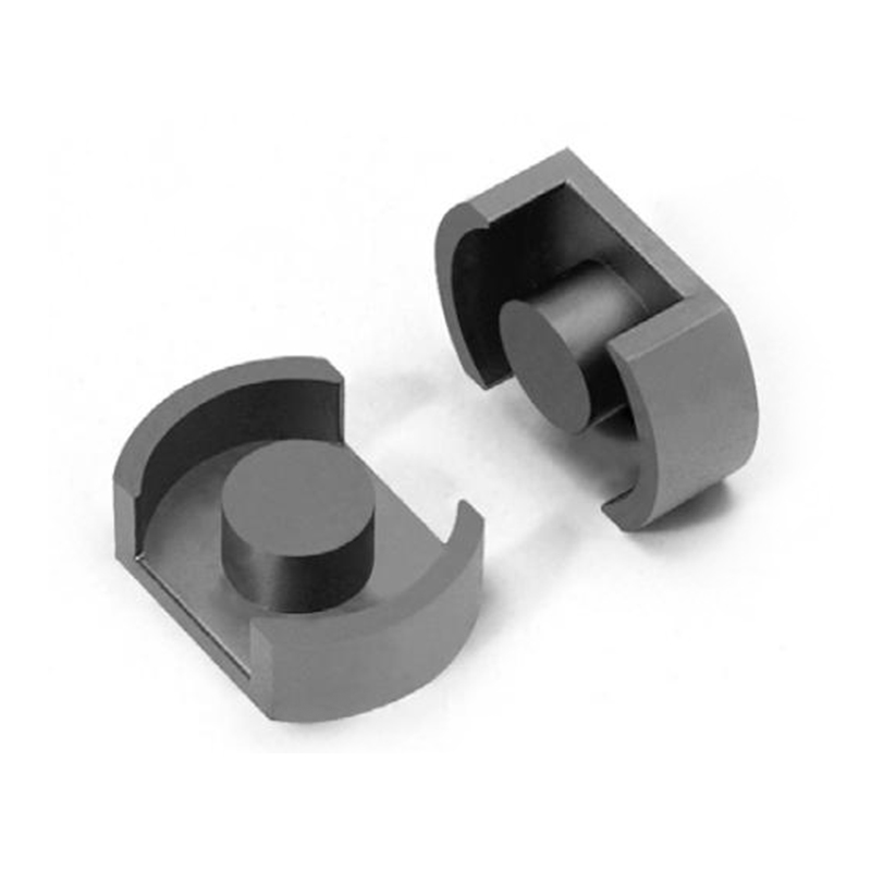
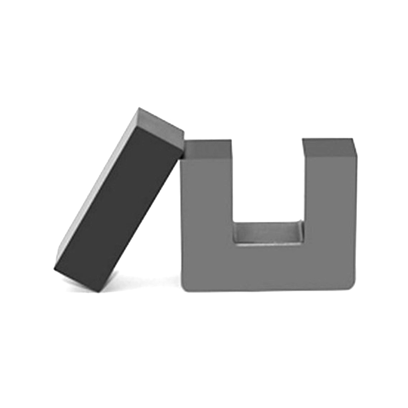
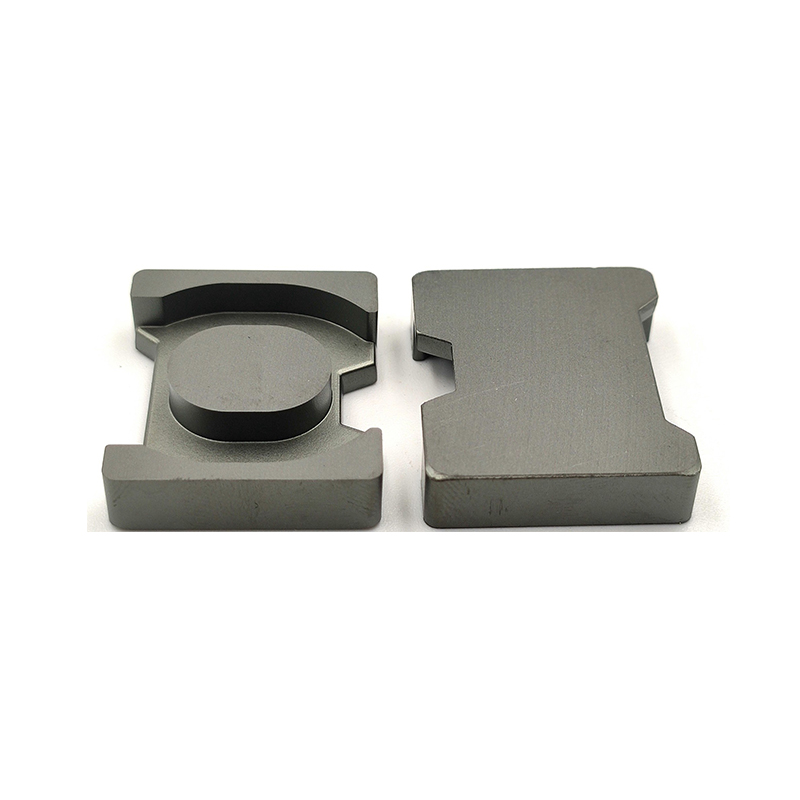
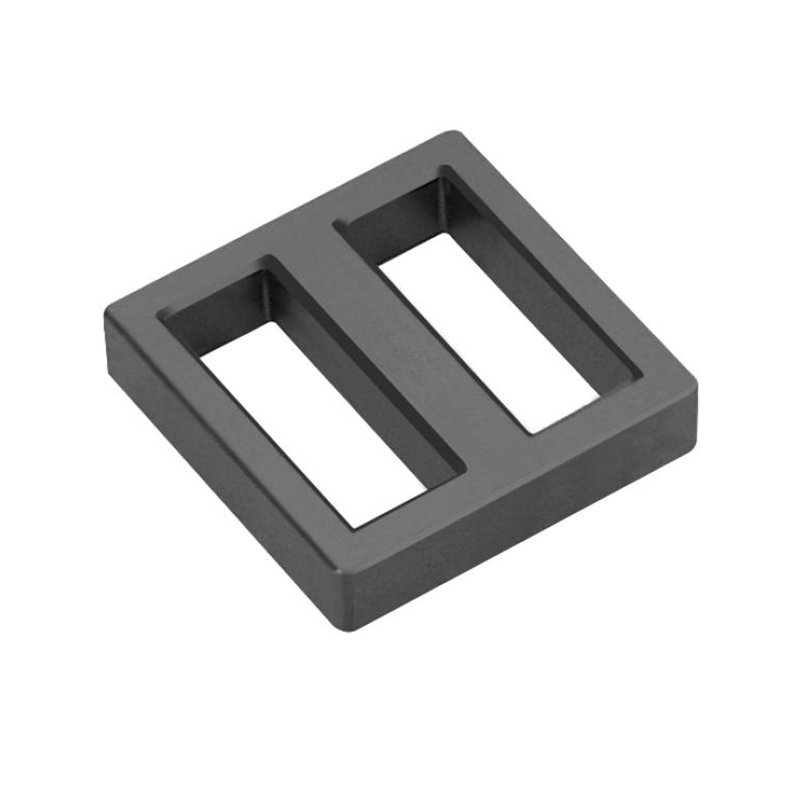
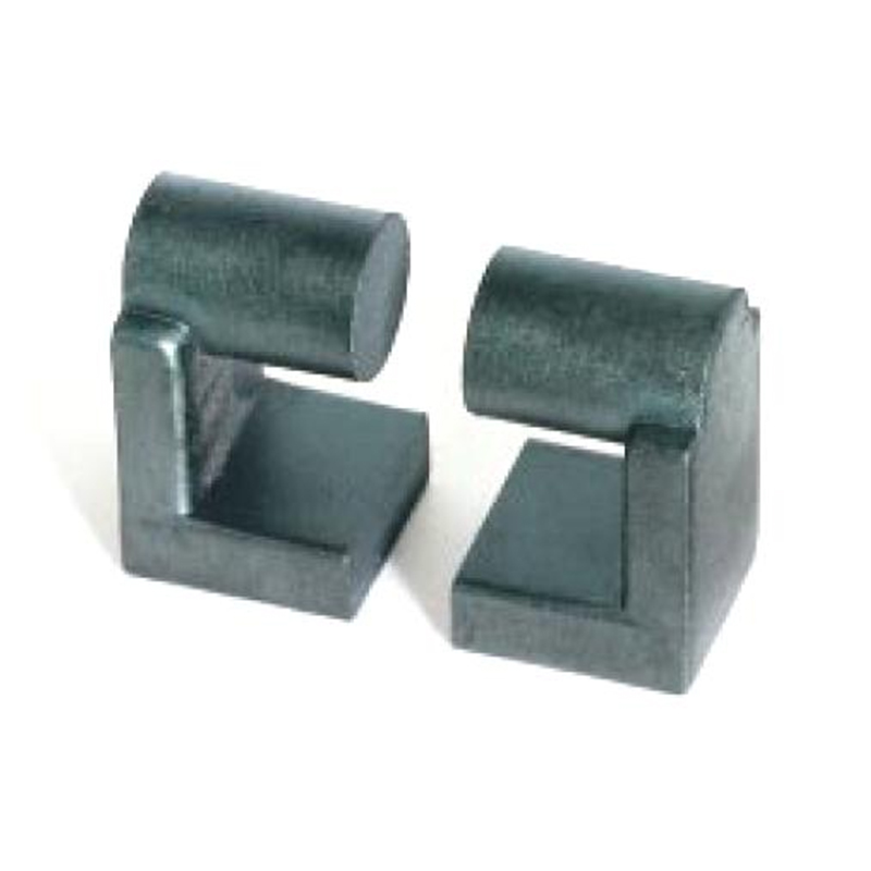
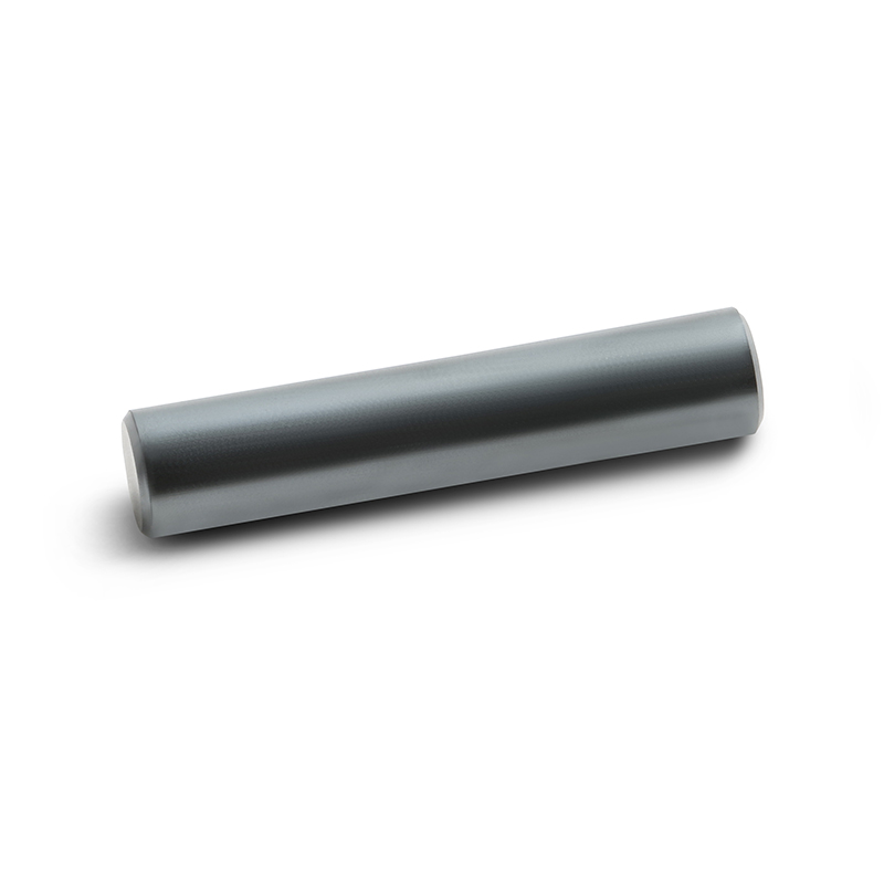
Mn-Zn Power Ferrite Cores for Inductors Transformers and MotorsCompare Mn-Zn power ferrite shapes, dimensions, magnetic parameters, and AL values for inductors, transformers, and motors where loss and cost favor MnZn.View Product →Nickel zinc ferrite enters the picture above a few megahertz, where MnZn resistivity is no longer sufficient. A practical comparison of MnZn and NiZn core types helps, but the short version is that NiZn trades saturation flux density for frequency headroom. Below 1 MHz it usually loses on both loss and cost.
Pick the material for the frequency the converter actually switches at, and for the core temperature the enclosure actually allows. Those two numbers eliminate most of the catalogue before the winding is even discussed.
The Design Loop: From Requirement to Wound Component
A custom magnetics program moves through five stages, and each stage can send the design back to the one before it.
Requirement capture. Inductance at a stated bias current, switching frequency, ambient temperature, height and footprint limits, isolation class, and the applicable safety standard. Missing one of these usually surfaces as a failed prototype two weeks later.
Material and geometry selection. Core family, grade, and shape are chosen to fit the loss budget inside the available volume. This is where the air gap length is set, because gap controls both inductance and saturation margin.
Winding and loss modelling. Turns count, wire gauge, and interleaving are balanced against window area. Copper loss, fringing loss near the gap, and leakage inductance are estimated together rather than one at a time.
Prototype and bench verification. Inductance versus bias current, temperature rise at full load, and switching waveform quality are measured. The bias sweep is the step most often skipped, and the one that most often changes the design.
Qualification and repeatable production. Insulation testing, thermal cycling, and process documentation. A design that works on one bench but cannot be wound the same way in volume is not finished.
Designs that stop after stage three tend to reappear as field returns, because the bias sweep and the thermal soak reveal problems that a single-point inductance measurement cannot.
What to Put in a Custom Magnetics RFQ
A complete RFQ states the operating conditions, not just the target inductance, because the same inductance value can be built in several ways with very different behaviour.
| Parameter | Typical Range | Why It Changes the Design |
| Inductance | 10 uH to 470 uH | Sets turns count and therefore window fill and copper loss |
| Inductance tolerance | plus or minus 10 to 20 percent | Drives gap tolerance and core sorting cost |
| DC bias current | 1 A to 20 A and above | Determines saturation margin and whether a gapped core is required |
| Switching frequency | 20 kHz to 1 MHz | Selects the material family and the wire strategy |
| Ambient and rise limit | 40 C ambient, 40 to 60 C rise | Caps total allowed loss, which constrains core volume |
| Height above board | 4 mm to 30 mm | Eliminates core shapes that would otherwise be first choice |
| Insulation class | Class B, F, or H | Sets the wire enamel and the creepage distances |
Quoting an inductance alone is the most common cause of a design that passes on the bench and fails in the enclosure. Bias current and temperature rise belong in the first email, not the second round.
Sourcing Risk and Quality Signals
The quality risk in a custom magnetics program sits mostly in process control, not in the design itself.
Two suppliers can build the same drawing and deliver very different parts, because winding tension, gap grinding tolerance, and sintering profile control all shift the final inductance distribution. When a program is going into volume, the questions worth asking are about the process, not the datasheet:
- Which management system certifications are actually held, and for which product lines
- Whether the supplier manufactures the powder, the core, and the wound component, or buys one of those stages in
- How inductance is verified in production, by sampling or by full test
- What the change notification process looks like when a core grade or a wire supplier changes
A vertically integrated supplier that produces ferrite powder, sintered cores, and finished transformers under one roof has fewer handover points where a material substitution can go unnoticed. That matters most for programs in automotive or industrial power, where an out-of-tolerance inductor is not a cosmetic issue.
For programs moving from prototype to volume, it is worth requesting a design review before the drawing is frozen, because a gap or wire change is cheap at prototype stage and expensive after qualification.
Ask for the inductance distribution from a production lot, not a single sample measurement. The width of that distribution tells you more about a supplier than any certificate on the wall.
Frequently Asked Questions
How long does a custom magnetics design typically take?
From a complete requirement set, a first prototype usually takes a few weeks, with the bulk of that time going into material selection and winding trials rather than the drawing itself. Programs that stall are almost always missing a bias current figure or a temperature limit, which forces the design loop to restart.
Can a custom magnetic always beat a catalogue part on cost?
Not at low volume. Custom tooling, gap grinding setup, and qualification effort carry fixed costs that a catalogue part spreads across thousands of customers. The economics shift once the annual volume is high enough, or once a catalogue part forces extra filtering, extra heatsinking, or a larger enclosure.
Is a gapped core always better for DC bias performance?
Usually, but not unconditionally. A gap raises the saturation margin and flattens the inductance versus current curve, which is what a switching converter wants. It also introduces fringing flux near the gap, which adds loss in the adjacent winding turns unless the winding is spaced away or the gap is distributed across the core.
What single measurement best predicts whether a design will survive?
Temperature rise at full load with the final enclosure in place. Inductance, saturation, and loss all influence it, and it is the one number that reflects how the magnetic behaves in the real thermal environment rather than on an open bench.
Previous Post
No previous article
Next Post
Steinmetz Formula Explained: Coefficients, Fitting and Core Loss Limits