
 English
 한국어
한국어 中文简体
中文简体Home / News / Industry News / DC Bias Explained: How It Affects Inductors, Capacitors, and Ferrite Cores
DC Bias Explained: How It Affects Inductors, Capacitors, and Ferrite Cores
Content
Measure a 22 uH output choke on the bench at light load and it reads exactly as designed. Run the same converter at full load, with 8 A of direct current flowing steadily through the winding, and the effective inductance can fall to 15 uH or lower. Nothing has failed: the copper is intact, the core is not cracked, and the housing sits within its temperature rating. The inductor is simply responding to DC bias.
The conclusion comes first: DC bias is the mean, or DC component, of a waveform, and in a magnetic component it shifts the core's operating point toward saturation. As that point moves, permeability falls, and inductance falls with it, often long before any visible symptom appears. For engineers specifying ferrite cores for power supplies, automotive converters, and EMI filters, designing around this effect is what separates a converter that holds its ripple budget in the field from one that misbehaves on a hot production line. The rest of this article explains what the term means across electronics, why capacitors and magnetic cores react so differently to it, and which design choices keep inductance stable under load.
What DC Bias Actually Means
DC bias, also called the DC component, DC offset, or DC coefficient, is the mean value of a waveform. A sine wave centered on zero has no bias. Superimpose a steady 8 A of direct current on top of the switching ripple and the average current sits at 8 A; that constant offset is the bias.
A waveform with zero mean is described as DC balanced, a property that matters in communications links, where a residual offset wastes signal swing, and in audio paths, where sustained offset feeds energy into a loudspeaker as heat instead of sound.
Biasing in the broader sense means setting that mean deliberately. A transistor stage is biased to a quiescent point so the AC signal swings around it inside the linear region. A power inductor follows the same logic with magnetic consequences: direct current in the winding produces a steady magnetizing force (H = NI/le, with N the turn count, I the current and le the effective magnetic path length) that pins the core at a fixed position on its B-H curve while ripple swings a small loop around it.
One Term, Two Very Different Component Behaviors
In ceramic capacitors, DC bias is a voltage effect. Class 2 dielectrics built on ferroelectric barium titanate lose effective capacitance as the applied field restricts polarization, so a nominal 10 uF part may deliver only half of that at rated voltage. Designers absorb the effect by derating voltage, upsizing the case, or specifying a more stable dielectric class.
In inductors, the same term describes a current effect. Direct current through the winding drives the core toward saturation, permeability falls, and inductance falls with it. Datasheets capture this as an inductance-versus-DC-bias curve, often paired with a rating such as an inductance drop of no more than 30 percent at rated current.
Both effects share one practical trait: a component measured at zero bias can look excellent and still be marginal in the circuit. Verification has to happen under realistic bias conditions, not on an idle bench.
What Happens Inside a Ferrite Core Under DC Bias
At zero current, a soft ferrite core sits at the origin of its B-H loop, where permeability is highest and the curve is steepest. DC bias moves the operating point up that curve. While the point remains on the steep slope, inductance barely changes. As the point climbs into the knee of the curve, the minor loop traced by the ripple current tilts progressively flatter: incremental permeability drops, and measured inductance follows it down. Push past the knee and the core saturates, inductance collapses toward the air-core value, ripple current spikes, and both switch stress and core heating rise quickly.
Temperature compounds the problem. Saturation flux density falls as the core heats up: a MnZn power ferrite that carries on the order of 500 mT at 25 °C typically loses roughly a fifth of that by 100 °C. A current rating verified at room temperature can therefore drift into saturation inside a sealed enclosure on a hot day. Suppliers experienced in power materials respond by publishing inductance-versus-bias data at several temperatures rather than a single figure.
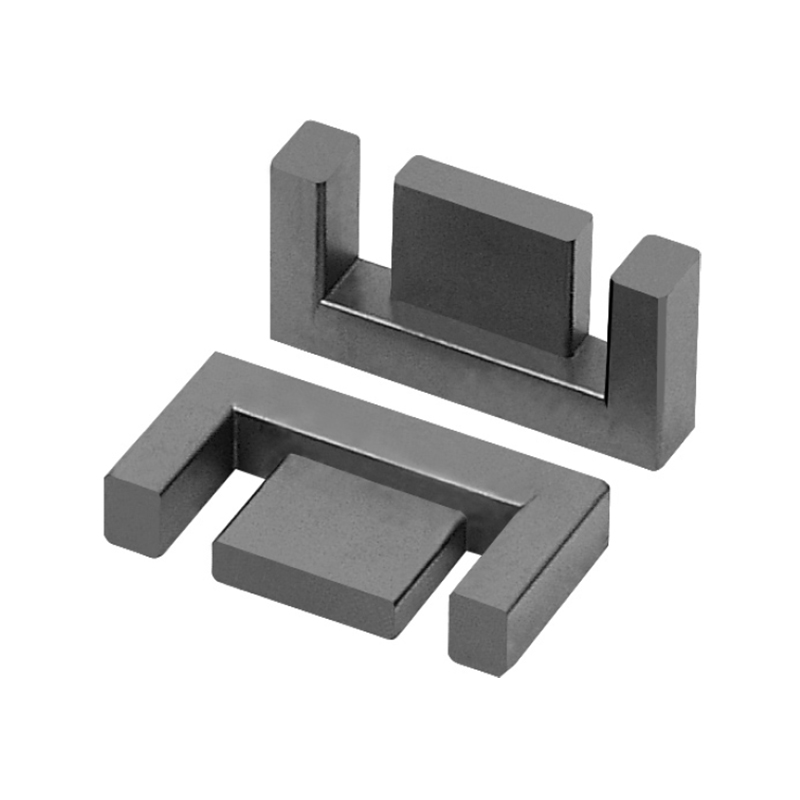
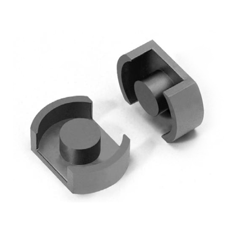
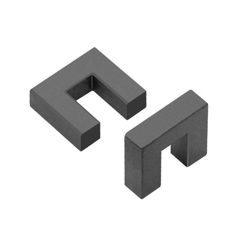
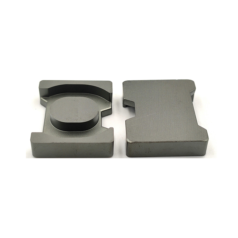
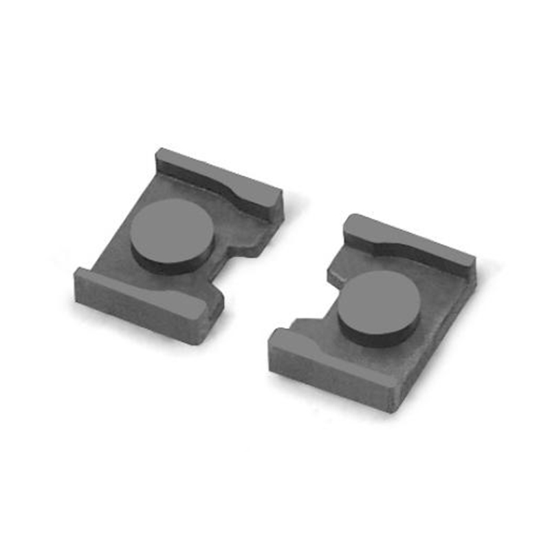
 MnZn Power Ferrite CoresPower ferrite cores carry DC-biased windings in transformers and inductors, where saturation worsens as core temperature rises. Yaorun publishes bias behavior across temperatures, making these cores worth review for hot, enclosed power circuits.View Product →
Applications Where DC Bias Sets the Limits
Almost every power electronics circuit has at least one winding carrying meaningful direct current, but the pressure points differ by function.
Power conversion chokes
Output inductors in buck converters and comparable topologies carry the full load current continuously, with triangular ripple riding on top. The inductance that remains at full load, not the zero-bias value, determines ripple current, peak switch current, and output ripple. A choke sized from the zero-bias figure can lose its entire margin at rated load.
Automotive power stages
Onboard chargers, 48 V DC-DC converters, and battery-management power stages combine high current, high ambient temperature, and long service life. Because saturation flux density drops as temperature rises, a rating that holds at room temperature may not hold in an engine bay in summer. Buyers at this level also expect suppliers to operate under automotive quality systems, so certification records belong next to the electrical data when qualifying a core vendor.
EMI filters and common-mode chokes
Common-mode chokes are designed so differential current cancels between windings, yet layout asymmetry and leakage inductance expose the core to a net DC component in real boards. The material must keep enough permeability under that residual bias to maintain impedance, which is where high-permeability MnZn grades earn their place in power-entry and data-line filters.
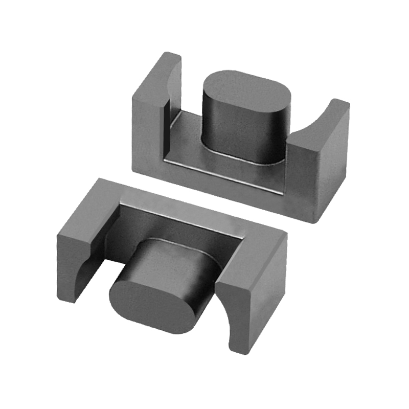
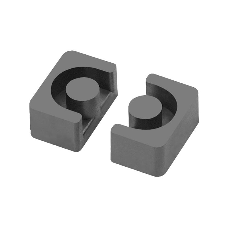
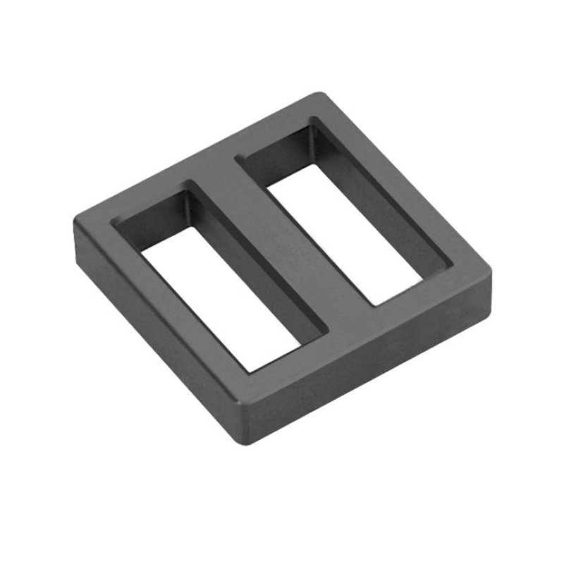
High Conductivity Mn-Zn Ferrite CoresHigh-permeability MnZn grades keep impedance under the residual DC bias that common-mode chokes see from layout asymmetry. This product fits power-entry and data-line filters where differential currents partially cancel but net bias remains.View Product →
The table below condenses the typical bias conditions and the material capability each application demands.
| Application | DC bias condition | Key material requirement |
|---|---|---|
| Buck converter output choke | Continuous load current plus switching ripple | High saturation flux density, low core loss at the switching frequency |
| Automotive DC-DC and onboard charging | High current in a hot environment | Saturation flux density retained at temperature, automotive-grade process control |
| Common-mode EMI choke | Small residual differential current from imbalance | Permeability retained at low bias, high resistivity |
| LED driver and adapter chokes | Continuous current in compact, sealed housings | Predictable inductance roll-off, stable low loss |
Design Levers for Managing DC Bias
Four levers dominate DC bias design, and most practical solutions combine two or three of them.
| Lever | Effect on DC bias behavior | Trade-off |
|---|---|---|
| Introduce an air gap | Shears the B-H loop so more ampere-turns are needed to reach saturation, and stabilizes inductance against temperature and part variation | Lower permeability requires more turns, which adds copper loss and resistance |
| Specify a high-saturation material | Moves the knee of the curve outward and postpones roll-off | Grade cost, and loss must match the switching frequency |
| Increase core cross-section | Reduces magnetizing force for the same ampere-turns | A larger, heavier and more expensive assembly |
| Reduce ripple and imbalance | Keeps the operating point lower on the curve | Constrained by topology, layout and cost |
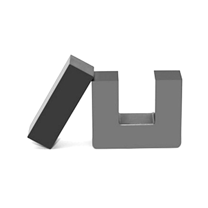
Gapping deserves particular attention because it is the most common lever and the easiest to get wrong. A discrete gap stabilizes inductance across temperature and production tolerance, but it lowers effective permeability sharply, so the winding needs more turns to hit the target inductance. That adds copper loss, and the fringing field around the gap introduces its own losses at high ripple. Choosing between gapped and ungapped MnZn ferrite cores therefore depends on how much bias the winding sees and how stable the inductance must remain across the full temperature range.
Choosing a Material Grade for High-DC-Bias Service
Material grades decide where the knee of the B-H curve sits and how fast inductance droops as it is approached. MnZn power ferrite grades are engineered for precisely this regime: high saturation flux density combined with low loss at the switching frequencies typical of power conversion, from roughly 25 kHz to several hundred kilohertz. Within a supplier's portfolio, some grades are tuned for high superimposed current, meaning they retain more of their zero-bias inductance at a given DC load, while others trade that margin for minimum loss at higher frequency.
Because chemistry and grain structure are fixed at the powder stage, the powder line upstream sets the ceiling on what a grade can achieve. Manufacturers that produce their own ferrite powder can tune composition and microstructure batch after batch, which matters when a bias curve has to stay in tolerance over years of production. Yaorun Electronics is structured this way, producing ferrite powder, cores, and wound transformers in one supply chain, with YR-series materials spanning low-loss, wide-temperature, high-superimposed and high-permeability families, and with participation in the national standardization committee for ferrite materials.
Soft Mn-Zn Ferrite PowderPowder chemistry and grain structure set the ceiling on core performance, so in-house powder production keeps DC-bias curves in tolerance across production batches. Yaorun's YR series spans low-loss, wide-temperature, and high-permeability grades.View Product →
When evaluating any grade, ask for the inductance-versus-DC-bias curve measured at your operating temperature and switching frequency, then cross-check the five specifications engineers usually review first when qualifying a ferrite core. A single saturation-current number is a summary, not a substitute for the curve.
Practical Takeaways
DC bias is not an exotic phenomenon. It is the ordinary consequence of passing direct current through anything magnetic, and the failures it produces, from sagging inductance to rising ripple and, in the worst cases, thermal runaway, are all preventable with margin and verification. Three habits cover most of the risk:
- Verify inductance under the DC bias and temperature the part will actually experience, not only at zero current.
- Leave saturation margin for temperature, since a rating that holds at 25 °C may fail to hold at 100 °C.
- Select the material grade and the gap together, because each one changes how the other behaves.
Handled together, those habits turn the bias column on a datasheet into a managed design input rather than a surprise discovered during production testing.
Previous Post
PFC Boost Converter Design: Ferrite Core Selection and Practical Guide
Next Post
Mn-Zn High Conductivity Ferrite: Properties, Applications and Selection Guide