
 English
 한국어
한국어 中文简体
中文简体Home / News / Industry News / PFC Boost Converter Design: Ferrite Core Selection and Practical Guide
PFC Boost Converter Design: Ferrite Core Selection and Practical Guide
Content
A 1,200 W industrial power supply without power factor correction can draw a severely distorted line current, wasting energy and adding harmonics that disturb other equipment on the same grid. A PFC boost converter solves this. It shapes the input current into a near-sinusoidal waveform, raises the power factor to above 0.98, and keeps total harmonic distortion low enough to satisfy IEC 61000-3-2. For the designer, the most important part of that converter is the boost inductor, and the most important decision inside that inductor is the ferrite core.
What a PFC Boost Converter Does
The boost PFC stage sits between the rectifier bridge and the main bulk capacitor. It uses a standard boost topology: a power switch, a diode, an output capacitor, and an inductor that stores and releases energy. The control circuit modulates the switch so that the average inductor current follows a sinusoidal reference proportional to the instantaneous line voltage. The output of the stage is regulated to a fixed DC value, usually 380 to 430 V DC, so the downstream DC-DC converter always sees a constant input.
One constraint is easy to miss: the output voltage must always be higher than the peak of the highest line voltage the design must tolerate. If the output drops below the line peak, the converter loses control of the input current and heavy distortion returns. For a 277 V AC input, for instance, the peak exceeds 390 V, so a 400 V DC bus is the practical floor.
Two operating modes dominate. In continuous conduction mode (CCM), the inductor current never falls to zero and the switching frequency is usually fixed between 65 kHz and 150 kHz. In boundary conduction mode (CrCM), the current returns to zero on every cycle and the frequency varies. Both modes need a core that handles a large DC bias without saturating and that keeps core loss under control at the operating frequency.
Why the Boost Inductor Decides Performance
The boost inductor carries the full input current. Unlike a transformer in an isolated converter, it must store significant energy and hold its inductance while a large DC bias current flows. These requirements push the design in opposite directions: high inductance means more turns, but more turns increase winding resistance and DC copper loss.
The practical sequence starts with the ripple current. In CCM designs, engineers typically choose an inductance that produces roughly 20 % to 40 % of the peak line current as ripple. That balances switch stress, magnetic size, and EMI filtering effort. Once the inductance target and peak current are known, the required air gap and effective core volume can be calculated.
Core saturation is a genuine procurement risk. During power-on, line transients, and load steps, the inductor current can overshoot well above the nominal peak. A core that saturates at 120 °C turns into a safety issue: inductance collapses, the current rises without limit, and the switch can fail. A well-chosen MnZn power ferrite core with a controlled air gap gives predictable saturation behaviour, low core loss, and a stable inductance over temperature, which is why it remains the default for CCM PFC boost stages up to several kilowatts.
Ferrite Material Properties That Matter in PFC
Not every ferrite grade works equally well in a boost PFC. The specs below separate a suitable power ferrite from a general-purpose magnetic material.
- High saturation flux density at operating temperature. The core must carry the peak PFC current plus ripple without losing inductance at 100 °C. Good MnZn power ferrites hold 350 mT or more at 100 °C and typically reach 420 to 470 mT at 25 °C. That headroom protects the converter from saturation under line swell conditions.
- Low core loss at the PFC switching frequency. At 100 kHz and a 100 mT flux swing, a quality MnZn power ferrite shows core loss in the range of 200 to 500 mW/cm³, depending on grade and temperature. A datasheet that only mentions loss at 25 °C is a warning sign, because the core will run far hotter than that in a real supply.
- Curie temperature well above the maximum working temperature. MnZn ferrites have a Curie temperature in the region of 200 °C or higher, so the permeability cannot disappear during an overtemperature fault.
- Initial permeability suited to a gapped structure. Since the boost inductor uses a wide air gap, the effective permeability is set mostly by the gap, not by the material itself. A material with an initial permeability of 2000 to 3300 keeps the turns count reasonable and the fringing effects manageable, which is why it is the norm for PFC boost designs.
MnZn power ferrite is the standard answer for PFC inductors from about 20 kHz to 500 kHz. The same material family is well suited to the isolated DC-DC transformer downstream, so a design team can qualify one core platform and reuse it across multiple power stages.
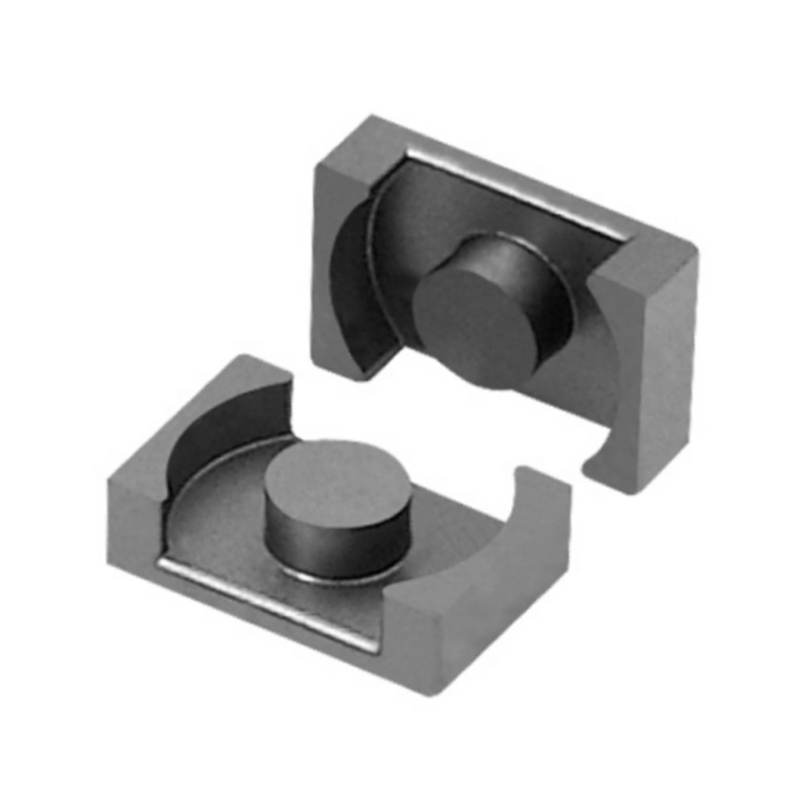
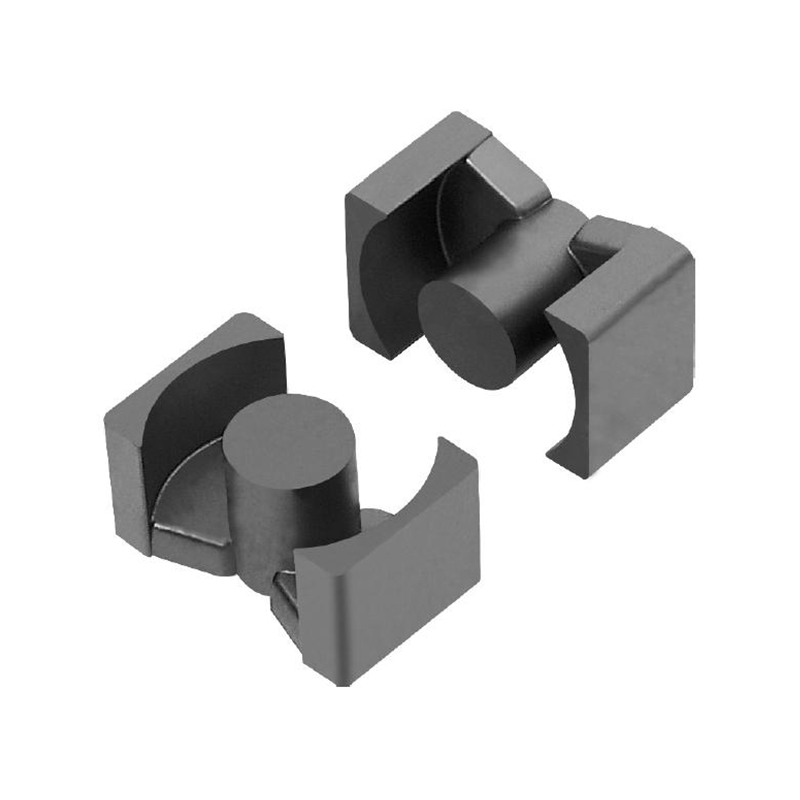
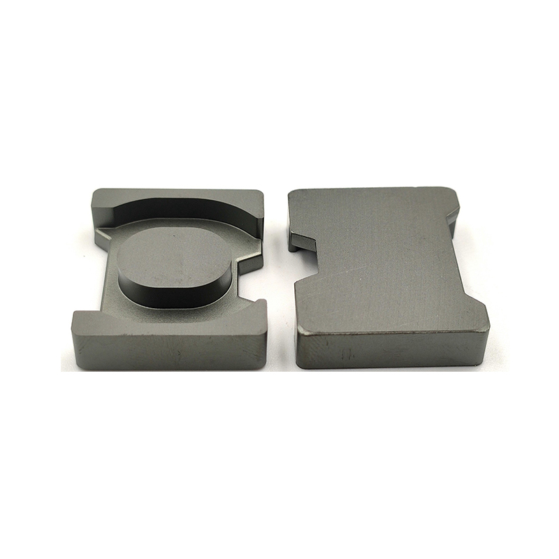
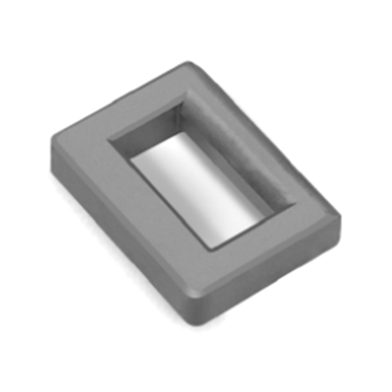
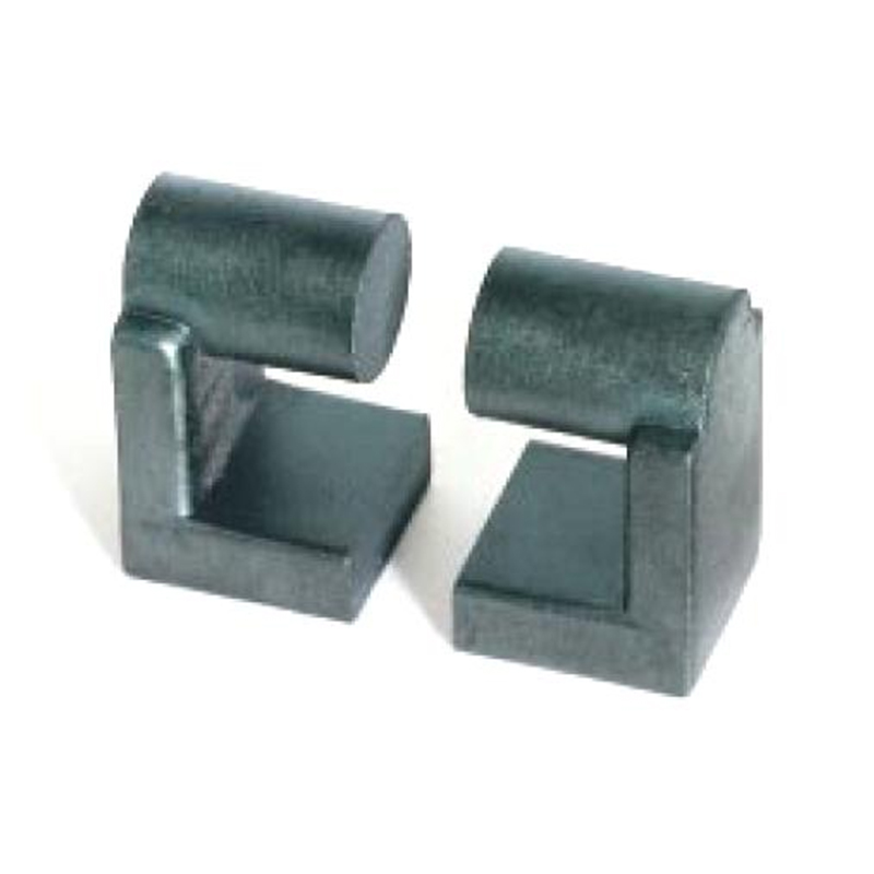
 MnZn Ferrite Cores for High-Frequency Power ConversionManganese-zinc ferrite cores from this manufacturer provide high saturation induction and low hysteresis and iron loss, supporting PFC inductors and isolated DC-DC transformers. The surrounding discussion highlights how core loss depends on frequency and ripple current, making material selection critical for thermal performance.View Product →
Core Loss and Temperature: Where Designers Get Surprised
Core loss is not a constant. It rises with frequency and with flux swing to the 2.4 to 3.0 power, depending on the grade. A small reduction in ripple current produces a visible drop in core temperature; a slight increase in inductance tolerance can send the core into a much hotter region than expected.
Real operating conditions also expose the core to high ambient temperature. The PFC inductor sits close to the rectifier and the power switch, so the surrounding air at the inductor can exceed 80 °C. Modern power ferrites are formulated with their minimum core loss in the 80 to 120 °C window precisely for this reason. The loss curve flattens out where the core actually works, giving the design thermal stability. If a candidate grade only provides loss data at 25 °C, treat it with suspicion.
The air gap deserves equal attention. A single large gap creates strong fringing fields around the winding, which induce eddy currents in the copper and produce hot spots. Good ferrite suppliers provide core shapes and gapping options that reduce this effect, including distributed gap configurations and precisely controlled AL values. The temperature difference between a poor gap design and a well-managed gap design can reach 20 °C or more. This is one reason to look closely at how MnZn ferrite reduces core losses in power electronics before committing to a core geometry.
What to Verify Before You Source Ferrite Cores for PFC
When you evaluate a ferrite supplier for PFC boost inductors, a short list of parameters determines whether the design will hold up in production. The difference between a good quotation and a problematic one is usually hidden in these numbers.
| Parameter | Typical target | Why it matters |
|---|---|---|
| Saturation flux density at 100 °C | ≥ 350 mT | Prevents inductance collapse at peak current and high ambient temperature |
| Core loss at 100 kHz, 100 mT, 100 °C | ≤ 500 mW/cm³ | Determines inductor temperature rise and overall converter efficiency |
| Initial permeability | 2000–3300 | Balances turns count against fringing loss in a gapped core |
| Curie temperature | ≥ 200 °C | Keeps magnetic properties stable under overtemperature faults |
| AL value tolerance | ±5 % or better | Keeps the inductor value and PFC control loop consistent in production |
| Gap options | Custom AL or measured gap | Gives the design team full freedom to set the effective inductance |
Beyond the datasheet, ask how the supplier controls batch consistency and whether core loss or saturation is verified on production batches. Some suppliers ship standard gapped cores with measured AL values; others expect you to implement the gap yourself. A supplier that offers both cores and finished magnetic components can usually give a clearer view of how the material will behave in the final inductor geometry.
The best way to reduce the risk of a late-stage inductor redesign is to start from a material family with proven saturation and loss behaviour. MnZn ferrite cores with high saturation and low loss cover the operating envelope of nearly every practical boost PFC design.
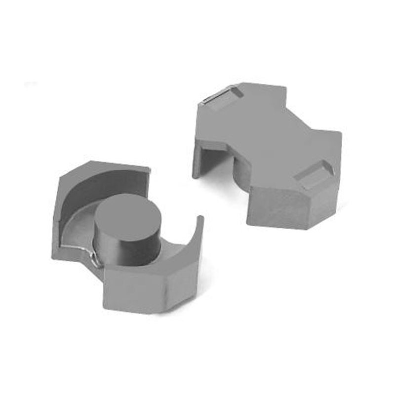
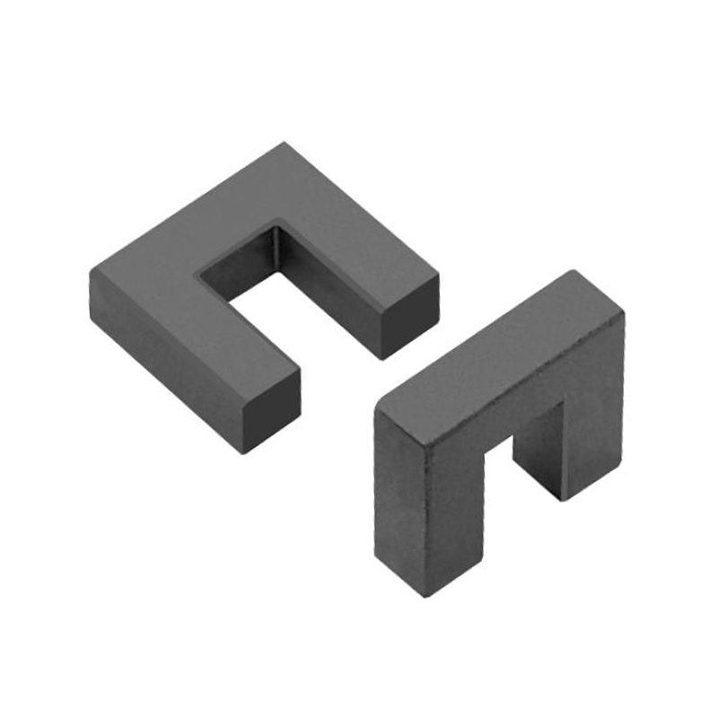
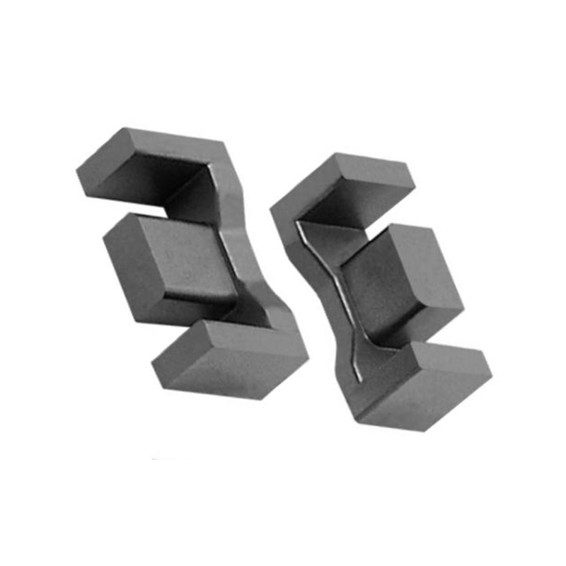
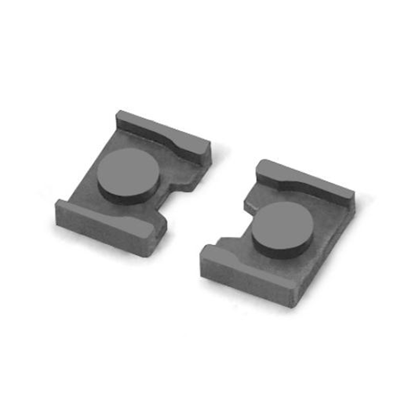
Soft Magnetic Ferrite Cores for Inductor and Transformer ApplicationsThese manganese-zinc soft ferrite cores feature high initial permeability and operate from 1 kHz to 10 MHz, suitable for inductors, transformers, and filters. The passage stresses verifying saturation and loss at worst-case temperature to prevent late-stage inductor redesign.View Product →A PFC boost converter is, in practice, a magnetic design project. Select the ferrite for the right frequency, verify saturation at the worst-case temperature, treat the air gap with respect, and then confirm the loss numbers on a real inductor. When you do, the converter will shape the line current cleanly, meet its efficiency target, and survive transients. Get the core wrong, and no control law can save the design.
Previous Post
EF20 Ferrite Core Guide: Dimensions, AL Value, Material and Applications
Next Post
DC Bias Explained: How It Affects Inductors, Capacitors, and Ferrite Cores