
 English
 한국어
한국어 中文简体
中文简体Mn-Zn Ferrite Properties and Selection Guide
Content
What Is Mn-Zn Ferrite?
A design engineer specifying a core for a 100 kHz flyback transformer usually starts with one material family: manganese‑zinc (Mn‑Zn) ferrite. It is a soft magnetic ceramic produced by sintering iron oxide with manganese oxide and zinc oxide. The term “soft” means the material can be magnetized and demagnetized with very little energy, which makes it fundamentally different from permanent magnets.
Mn‑Zn ferrite belongs to the broader class of soft ferrites, which split into two principal groups: Mn‑Zn and nickel‑zinc (Ni‑Zn). While both share a spinel crystal structure, Mn‑Zn grades rely on manganese and zinc cations to achieve high permeability and high saturation flux density. Ni‑Zn grades substitute nickel for manganese, giving up some permeability for dramatically higher electrical resistivity.
Because Mn‑Zn ferrite grains are semiconducting rather than insulating, the material is inherently suited to frequencies below a few megahertz, where eddy‑current losses remain manageable. Above that region, Ni‑Zn or other materials become necessary. This frequency boundary is the first decision point in any core selection process.
Core Characteristics of Mn‑Zn Ferrite
Engineers rarely select a magnetic material for a single number; they weigh a handful of interdependent properties. In the case of Mn‑Zn ferrite, four characteristics drive most decisions.
High Permeability and High Flux Density
Initial permeability values for power-grade Mn‑Zn ferrites typically range from 1,500 to over 10,000. A higher permeability directly raises inductance per turn, allowing smaller cores and shorter windings. Coupled with saturation flux densities up to roughly 500 mT at room temperature, these materials handle sizeable volt‑second products without saturating. That combination is exactly what line‑frequency and medium‑frequency power transformers require.
However, permeability is not constant; it peaks at a certain temperature and then declines. Engineers working above 80 °C often cross‑check the permeability‑versus‑temperature curve to avoid an unwelcome drop in inductance under load. Always request the permeability‑versus‑temperature graph from the ferrite supplier before locking in a core size.
Low Power Loss
Mn‑Zn ferrite excels below 2 MHz because its total loss — the sum of hysteresis and eddy‑current components — remains competitively low. Hysteresis loss scales with the area of the B‑H loop, so grades with low coercivity (often 10‑20 A/m) and low remanence minimize wasted energy per cycle. Eddy‑current loss is kept in check by the naturally moderate resistivity of the material and, in practice, by the core’s lamination‑like granular structure.
Modern power ferrites are classified by loss at a defined excitation: for example, a PC40‑equivalent grade might be rated for roughly 400 mW/cm³ at 100 kHz and 200 mT. When a design pushes into the hundreds of kilohertz, the loss‑density specification overshadows permeability in importance, because core temperature rise becomes the limiting factor.
Low Coercivity and Low Remanence
Transformers and inductors in switched‑mode supplies experience full bipolar flux swings. A material with high remanence would retain significant magnetization after each half‑cycle, forcing the control circuit to spend energy resetting the core. Mn‑Zn ferrite’s low remanence (often below 100 mT) and low coercivity make polarity reversal efficient, which is why push‑pull, half‑bridge, and full‑bridge topologies rely on it almost exclusively.
Mn‑Zn vs. Ni‑Zn: How to Choose
The choice between Mn‑Zn and Ni‑Zn ferrite boils down to frequency and the acceptable loss budget. A detailed comparison is available in our Mn‑Zn vs. Ni‑Zn ferrite selection guide, but the core trade‑offs can be summarized in a few data points.
| Property | Mn‑Zn Ferrite | Ni‑Zn Ferrite |
|---|---|---|
| Initial permeability | 1,500 – 15,000 | 10 – 2,500 |
| Resistivity | ~0.1 – 10 Ω·m | ~10⁴ – 10⁶ Ω·m |
| Usable frequency | < 2 MHz | 1 – 300 MHz |
| Typical uses | Power transformers, storage inductors, EMI chokes (low‑frequency) | RF transformers, antennas, high‑frequency EMI suppression |
| Relative cost | Lower | Higher |
For common‑mode chokes below about 70 MHz, Mn‑Zn is usually the economical choice because its high permeability delivers the required impedance with fewer turns. Above that frequency, Ni‑Zn takes over because its resistivity prevents excessive capacitive coupling and keeps impedance high.
The table clarifies the bandwidth boundary: if your switching frequency or harmonic content stays under 2 MHz, Mn‑Zn will almost always offer lower material cost and higher inductance per volume.
Typical Applications of Mn‑Zn Ferrite
Mn‑Zn ferrite cores show up wherever substantial power must be processed at frequencies from 50 Hz to about 2 MHz. The following are the most common roles:
- Power transformers in switch‑mode supplies, DC‑DC converters, and inverters. The material handles the high volt‑second product while keeping core loss manageable. For a closer look at the material properties that make this possible, see key material properties of Mn‑Zn ferrite for high‑frequency transformers.
- Energy‑storage inductors in buck, boost, and buck‑boost regulators, often with a gapped core to control the effective permeability and prevent saturation.
- EMI suppression using toroidal common‑mode chokes on power input lines. Mn‑Zn grades with permeability above 5,000 can achieve target impedance with minimal winding capacitance.
- Current transformers and pulse transformers, where low phase shift and good linearity up to a few hundred kilohertz are needed.
- Renewable energy equipment, including solar inverters and wind‑turbine converters, where high efficiency and long‑term thermal stability dictate the core choice.
Engineering Selection Checklist
Choosing the right Mn‑Zn ferrite grade for a specific design involves more than picking the highest permeability number. Follow the steps below to avoid common pitfalls:
- Confirm the operating frequency. If the fundamental exceeds 2 MHz, consider Ni‑Zn or a different material class. For most offline and industrial converters running below 500 kHz, standard power‑grade Mn‑Zn ferrite suffices.
- Identify the dominant loss mechanism. At low loads, permeability and magnetizing current dominate. At full load, core loss density (mW/cm³) drives temperature rise. Cross‑reference the material’s power‑loss curves at your peak flux density and frequency.
- Check the saturation boundary at worst‑case temperature. Saturation flux density falls as temperature rises. Compute the maximum volt‑second product across the whole operating temperature range and ensure the core stays below the saturation inflection point.
- Evaluate DC bias requirements. Inductors carrying significant DC current may need a gapped core. The gapped structure reduces effective permeability, so factor in the resulting inductance drop.
- Plan for thermal management. Mn‑Zn ferrite’s losses increase with temperature up to a minimum near 80–100 °C, then drop slightly before Curie temperature. If the core is likely to run above 100 °C, consult the loss‑versus‑temperature curve and consider forced cooling or a larger core.
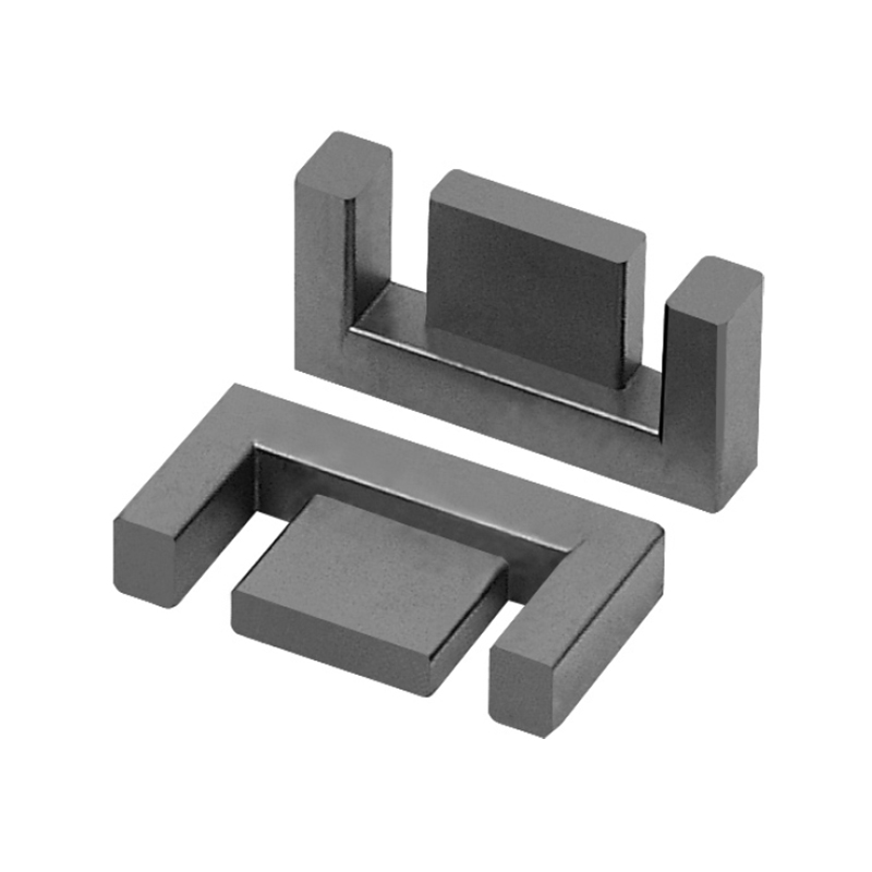
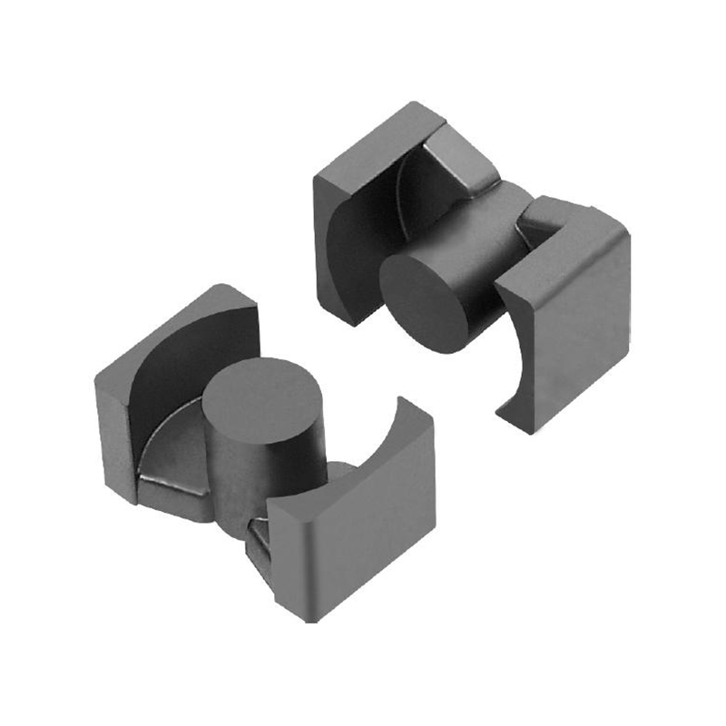
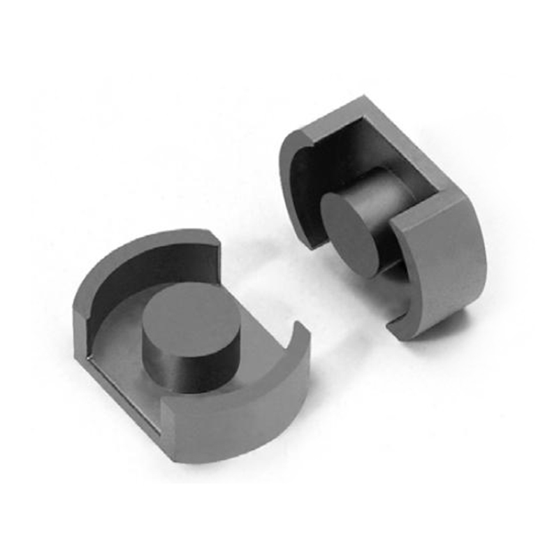
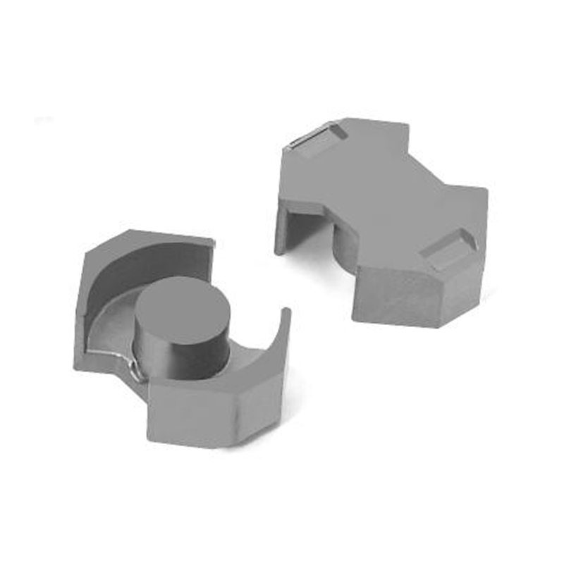
- Review mechanical and winding fit. Shapes such as E, ETD, RM, and toroids offer different power‑handling and shielding trade‑offs. Verify that the bobbin and winding window accommodate the required copper cross‑section for your current density target.
If your application demands a specific power‑grade material, you can browse the available Mn‑Zn power ferrite product series. For designs where higher electrical conductivity within the core offers an advantage, explore high‑conductivity Mn‑Zn ferrite in switching power supplies to understand the trade‑offs.
Conclusion
Mn‑Zn ferrite is the go‑to soft magnetic material when a design must deliver high inductance, low loss, and competitive cost at frequencies below 2 MHz. Its success in power conversion and EMI control rests on a specific combination of high permeability, low coercivity, and manageable loss density — a combination that no other material family duplicates at the same price point. The key to a reliable design is not to chase the highest datasheet number, but to align the material’s frequency, loss, and saturation characteristics with the actual operating envelope. Asking the supplier for full‑temperature loss curves and B‑H loops, not just room‑temperature data, often makes the difference between a prototype that works and one that fails in the field.
Previous Post
Soft Magnetic Ferrites: A Practical Selection Guide for Transformers and Inductors
Next Post
Soft Magnetic Ferrites: The Complete Guide for Engineers