
 English
 한국어
한국어 中文简体
中文简体Soft Magnetic Ferrites: Material Types, Core Specs & Selection Guide
Content
Every time a laptop charges, an EV battery absorbs power, or a solar inverter converts DC to AC, a soft magnetic ferrite core is working somewhere in that circuit. These ceramic components are rarely discussed outside engineering circles—yet they sit at the center of virtually every high-frequency power conversion system built today.
This article breaks down what soft magnetic ferrites are, which types matter for modern applications, how to read the key specs, and what to check when selecting a core for your design.
What Makes a Ferrite "Soft"
Soft magnetic ferrites are iron oxide-based ceramic compounds with the general formula MFe₂O₄, where M is a divalent metal such as manganese, zinc, or nickel. "Soft" refers to magnetic behavior, not physical hardness: these materials magnetize and demagnetize easily with minimal energy loss per cycle. That property—low coercivity—is exactly what makes them indispensable in AC and switching applications.
Unlike silicon steel laminations used in 50/60 Hz power transformers, ferrites have high electrical resistivity, which suppresses eddy current losses at higher frequencies. The tradeoff is lower saturation flux density (Bs ≈ 0.3–0.5 T vs. 1.8–2.0 T for silicon steel), so they are not suited for bulk power at line frequency—but they are the dominant choice anywhere the switching frequency climbs into the kHz–MHz range.
The Two Types Engineers Actually Use
Mn-Zn power ferrite cores and Mn-Zn high-permeability (high-conductivity) ferrite cover the majority of real-world designs. Here is how they compare:
| Property | Mn-Zn Power Ferrite | Mn-Zn High-Conductivity Ferrite |
|---|---|---|
| Typical frequency range | 25 kHz – 1 MHz | 1 kHz – 10 MHz |
| Initial permeability (µᵢ) | ~1500–3000 | ~5000–15000+ |
| Core loss (Pcv) | Optimized for low loss | Higher; not the priority |
| Primary use cases | SMPS transformers, power inductors, PFC stages | Common-mode chokes, broadband transformers, filters |
For frequencies above 10 MHz, nickel-zinc (NiZn) ferrites generally take over, as MnZn materials become too lossy. Below 1 MHz, MnZn is almost always the better choice—lower cost and higher flux density than NiZn in that range.
Reading Core Specs: The Numbers That Matter
Ferrite datasheets carry several parameters that directly affect design outcomes. The three most critical are:
- Inductance factor (AL) – expressed in nH/N². Multiply by turns squared to get inductance. For example, an EE13/6 core in YR48 material has AL = 1,050 nH/N²; 10 turns yields about 105 µH. This value is the starting point for any winding calculation.
- Effective cross-section (Ae) and path length (Le) – together they define the effective volume (Ve = Ae × Le). Core loss scales with Ve, so a smaller core running at higher flux density may actually run hotter than a larger core at lower density.
- Material grade – grades like YR28, YR48, and YR98 indicate initial permeability bands (roughly 2800, 4800, and 9800 respectively for high-conductivity types). Power ferrite grades are optimized for loss at specific frequency-temperature combinations.
As a practical reference: an EE42/15 core has Ae = 181 mm², Le = 97.3 mm, and Ve = 17,611 mm³—suitable for high-power transformer designs up to several kilowatts. A compact EE8.3/4 (Ae = 7 mm², Ve = 148.7 mm³) fits charger stages in the single-digit watt range. Matching the core volume to power throughput is the first step in any thermal-aware design.
Application Matching: Getting the Core Shape Right
Core geometry affects coupling efficiency, heat dissipation, and board footprint. The most widely used shapes and their advantages:
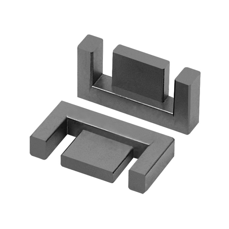
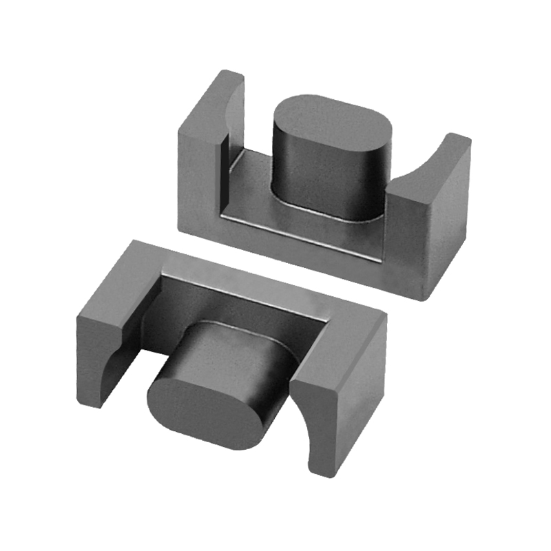
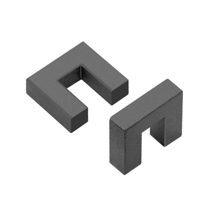
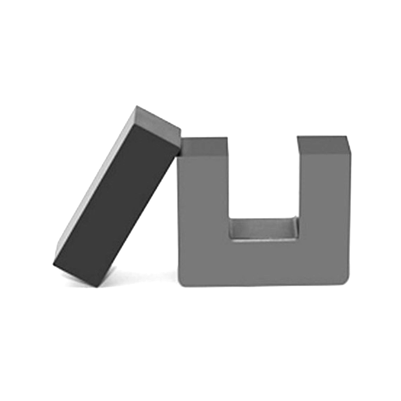
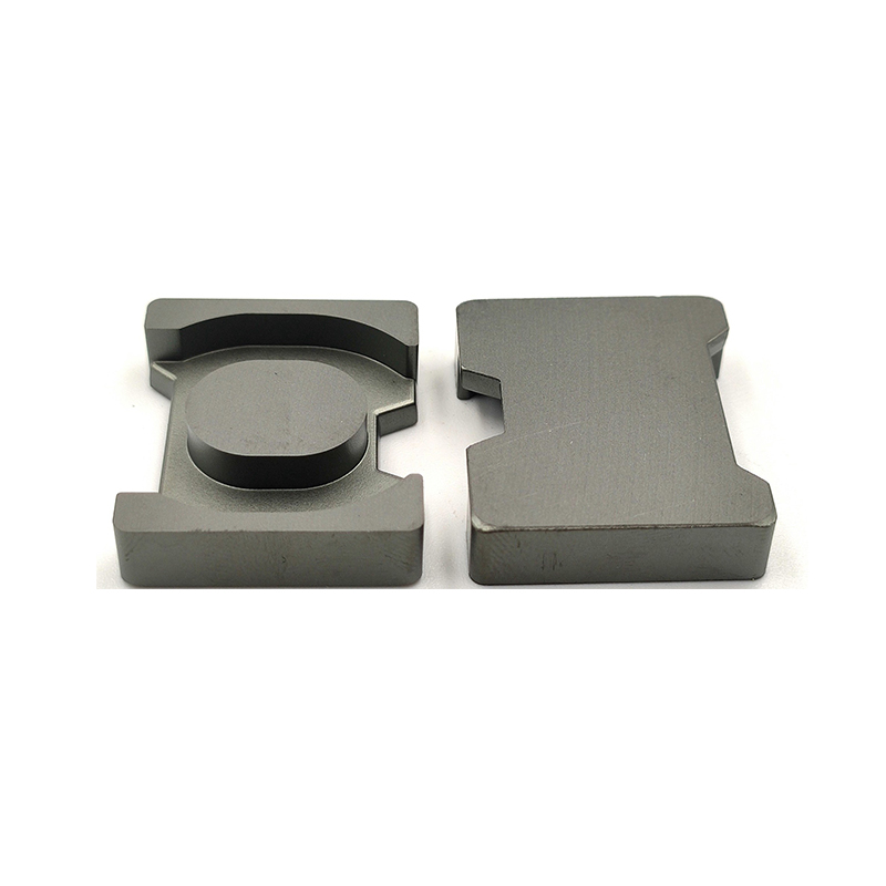
- EE / EF types – split into two E-halves, easy to wind, good for high-power SMPS transformers. EF variants have a rounded center post that reduces flux concentration and improves winding fill factor.
- EC / ER types – round center post for lower AC winding resistance; preferred in high-current, high-frequency inductors where proximity-effect losses matter.
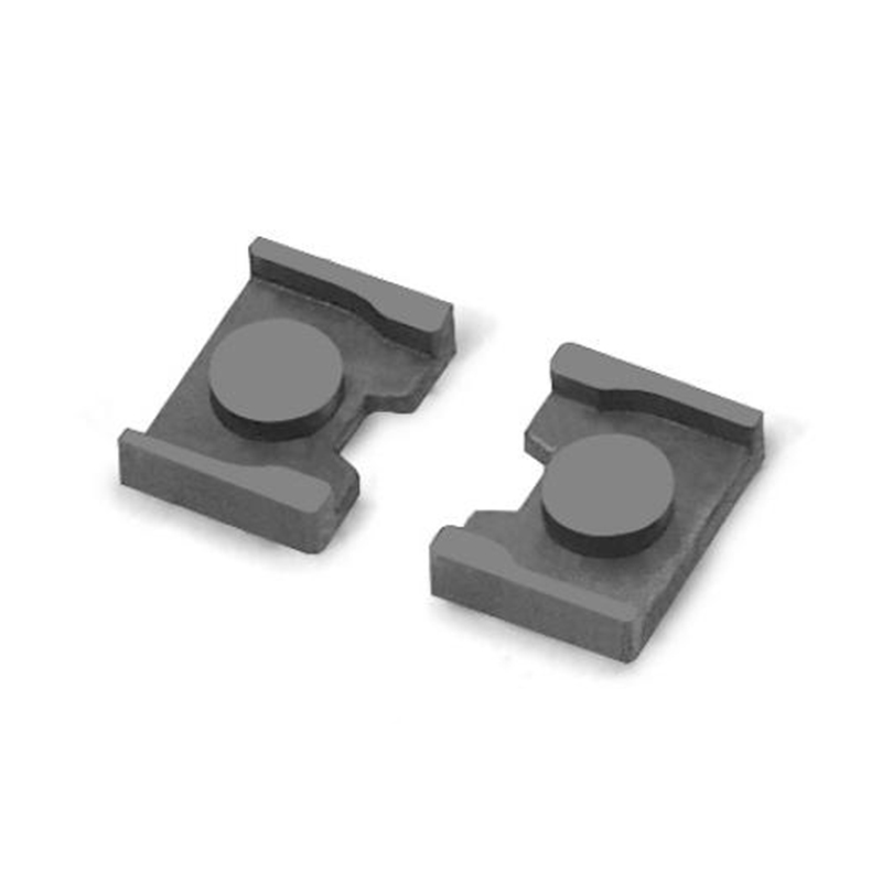
- EB types – elongated "boat" profile, suited for planar or low-profile magnetics in space-constrained designs.
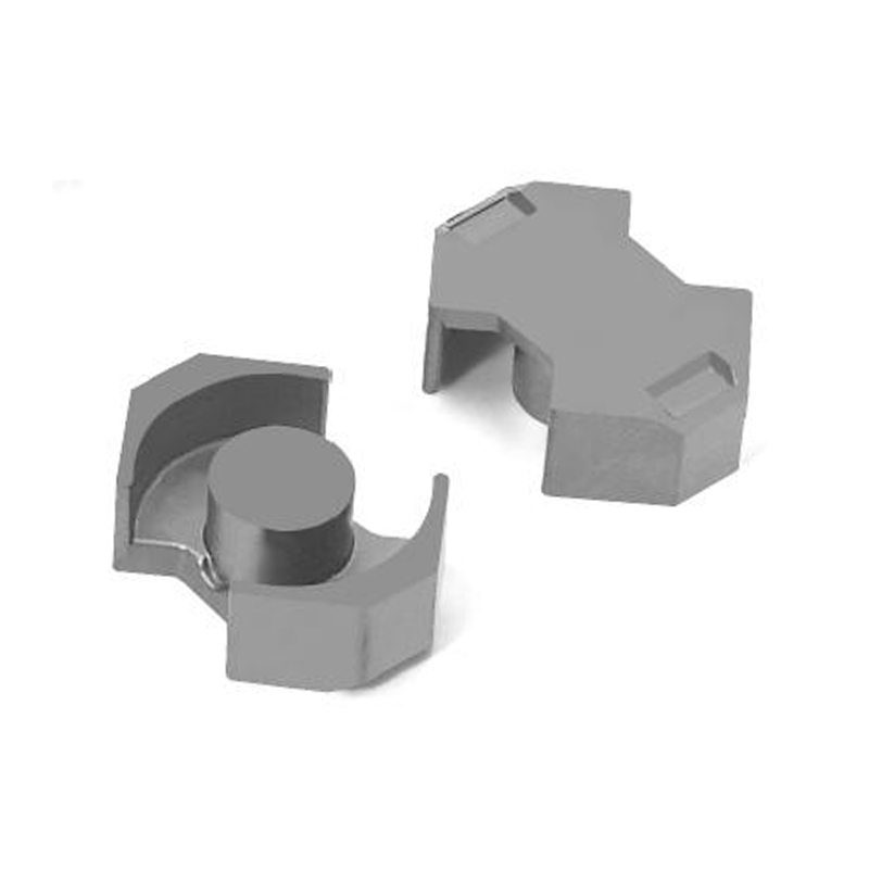
- PQ / PTS types – optimized surface area for heat transfer; often used in telecom power supplies where thermal management is critical.
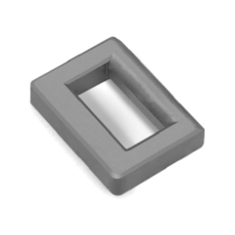
For common-mode inductors built with high-conductivity MnZn ferrite, toroidal or EB-type cores are typically preferred—they provide a closed magnetic path that maximizes common-mode impedance while minimizing leakage flux into adjacent components.
Three Practical Selection Rules
Engineers who work with ferrites regularly converge on a few rules that cut through the complexity:
- Start with operating frequency, then pick material. MnZn below 1 MHz, evaluate both MnZn and NiZn from 1–10 MHz, NiZn above 10 MHz. No amount of core geometry optimization compensates for using the wrong material family.
- Size for thermal headroom, not just inductance. Core loss (Pcv) increases steeply with temperature in ferrites. A core running near its Curie temperature loses permeability rapidly—this is a non-linear failure mode that standard inductance calculations do not flag.
- Verify AL under real operating flux density. Datasheets quote AL at low signal levels. In power applications, the core operates at significant AC flux density (ΔB), which causes permeability—and therefore AL—to shift. Always confirm inductance at the actual peak flux density for your design.
Where Soft Magnetic Ferrites Are Heading
Wide-bandgap semiconductors (GaN and SiC) are pushing converter switching frequencies higher—into the multi-MHz range in some designs. This is challenging the upper frequency limit of MnZn materials and accelerating development of lower-loss formulations. At the same time, EV traction systems and renewable energy inverters are creating demand for larger, higher-power ferrite assemblies that maintain stable permeability across wide temperature swings (−40°C to 125°C operating range is now common in automotive specs).
Ferrite core and transformer product lines are responding with tighter tolerance grades and improved material compositions that shift the loss minimum closer to 100°C—better aligned with real operating temperatures in enclosed power supplies. For design teams sourcing cores, the key question to ask suppliers is not just "what is the permeability?" but "at what temperature and frequency was this measured, and how does loss behave at my operating point?"
Soft magnetic ferrites are not glamorous. But they determine whether a power supply runs cool and efficient or hot and marginal. Getting the material type, core geometry, and operating point right—upfront—is the difference.
Previous Post
MnZn Ferrite Core Selection Guide: Properties, Types & Applications
Next Post
Ferrite Core Selection Guide: MnZn vs NiZn, Core Types & Applications